
Tool Steel Tempering and Isothermal Transformation
Two different temperature holds decide what a tool steel ends up as, and the micrographs below show both. The first is the temper that follows the quench, where the temperature and the number of tempers fix the hardness, the carbide type and how much retained austenite is left. The second is the isothermal hold in a salt bath at a temperature above the martensite start, which produces pearlite or bainite instead of martensite and is the route used for shock resisting grades such as S7 and O1 when distortion or cracking risk has to come down.
Why a tool steel is tempered straight after the quench
Quenching a tool steel to martensite leaves the section under very high transformation stress, and the temper is what relieves it. A tool steel that is left un-tempered after the quench can crack, and the risk rises with the quench rate and with any stress raiser in the geometry. Air hardening grades are less exposed to that risk, because the slow cooling that forms their martensite also relieves part of the stress on the way down, which is one of the practical reasons an air hardening grade is chosen for a complex die.
What each tempering temperature does
A large part of tool steel production is tempered between 175 and 230 °C, and at those temperatures the temper does little to the structure beyond relieving the quenching stress. The hardness barely moves and the micrograph looks almost the same as the as-quenched one, which is why a low temper is not the tool for a die that has to keep its hardness hot. Hot work and high speed steels are taken much higher instead, because their alloy content lets them resist softening, and at those temperatures the temper produces secondary hardening and changes the nature of the carbide.
The number of tempers is set by the alloy level. The lowest alloy tool steels take a single temper, normally 2 h for every 25 mm of section thickness. Higher alloy steels are usually tempered twice, and high speed steels three times, because the repeat tempers are what condition and stabilize the structure. The series below is O1 at four tempering temperatures, and the number printed with each plate is the hardness that came out of the same specimen.
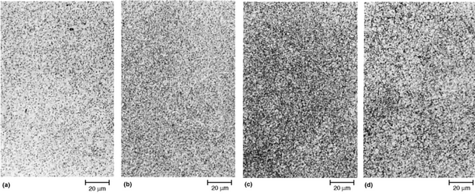
Tempering to about 540 °C produces only subtle differences in the structure as it appears under the light microscope. What does change is the speed at which the specimen etches and the darkness of the matrix. A pronounced structural change needs a temper just below the lower critical temperature, and a temper that high has no practical use on a tool or a die, apart from being an anneal.
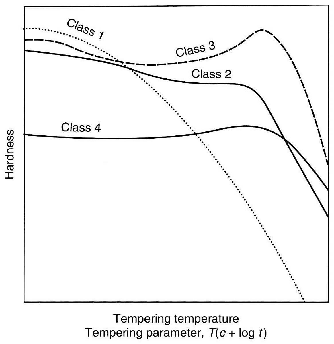
How far the hardness falls, and whether it falls at all, depends on the class the grade belongs to, and the classes are drawn out on one chart.
Carbide changes that light microscopy cannot show
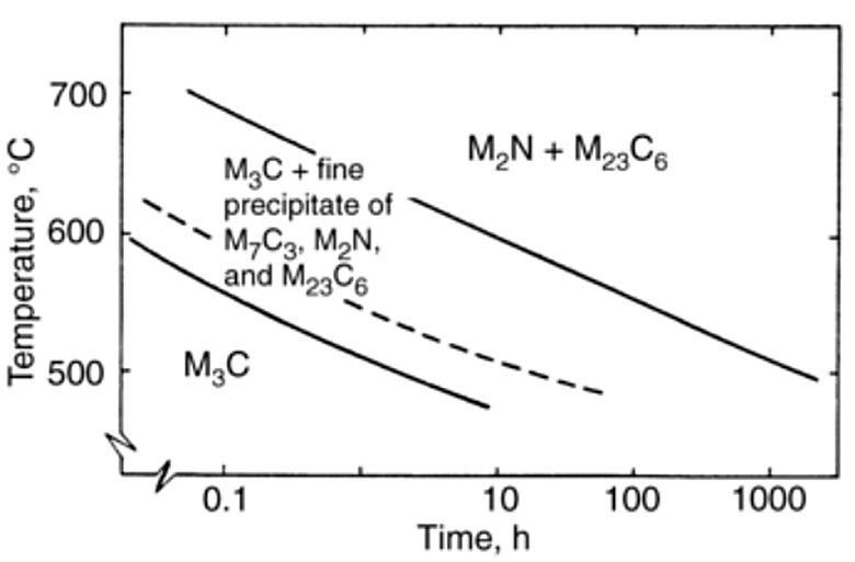
Where strong carbide forming elements are present, a high temperature temper changes the composition and the type of the carbide, and a light microscope cannot see it. The diagram below tracks that change in a 12% chromium martensitic steel, which is more heavily alloyed than type 420 and behaves the same way as the chromium tool steels. At low tempering temperatures the carbide present is M3C. As the temperature and the time increase it is replaced by M7C3 and then by M23C6, and M23C6 is the only one left at the top of the range. That steel also carried a high nitrogen content, and M2N nitrides were found in it. In tungsten high speed steels the same sequence runs further, with strong secondary hardening around 600 °C, and the diagram for those two steels is on the tool steel microstructure page.
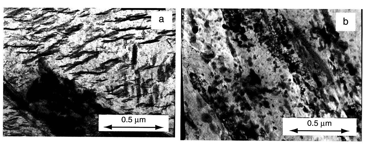
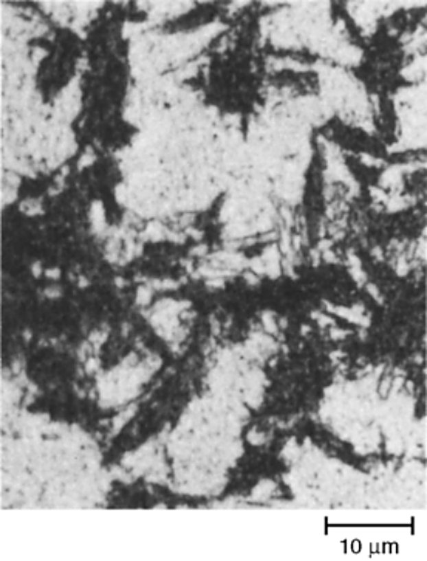
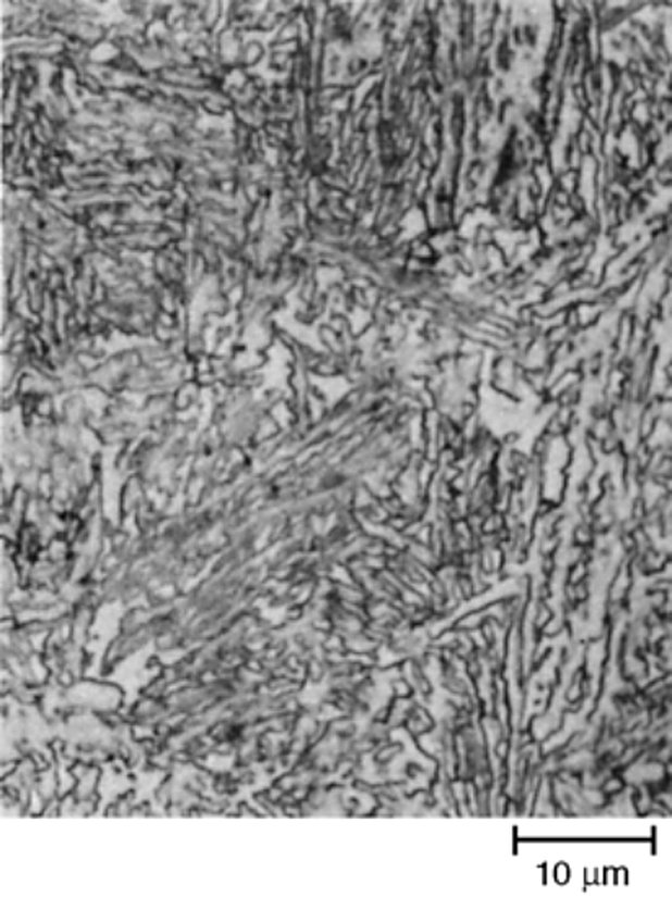
The carbide changes themselves are below the resolution of the light microscope, so they are followed in the transmission electron microscope instead. The two micrographs below are the same quenched steel, one tempered for 2 min at 300 °C and one for 1 min at 600 °C.
Secondary hardening is why a high speed steel is tempered hot rather than gently, and each of the carbide forming elements contributes to it.
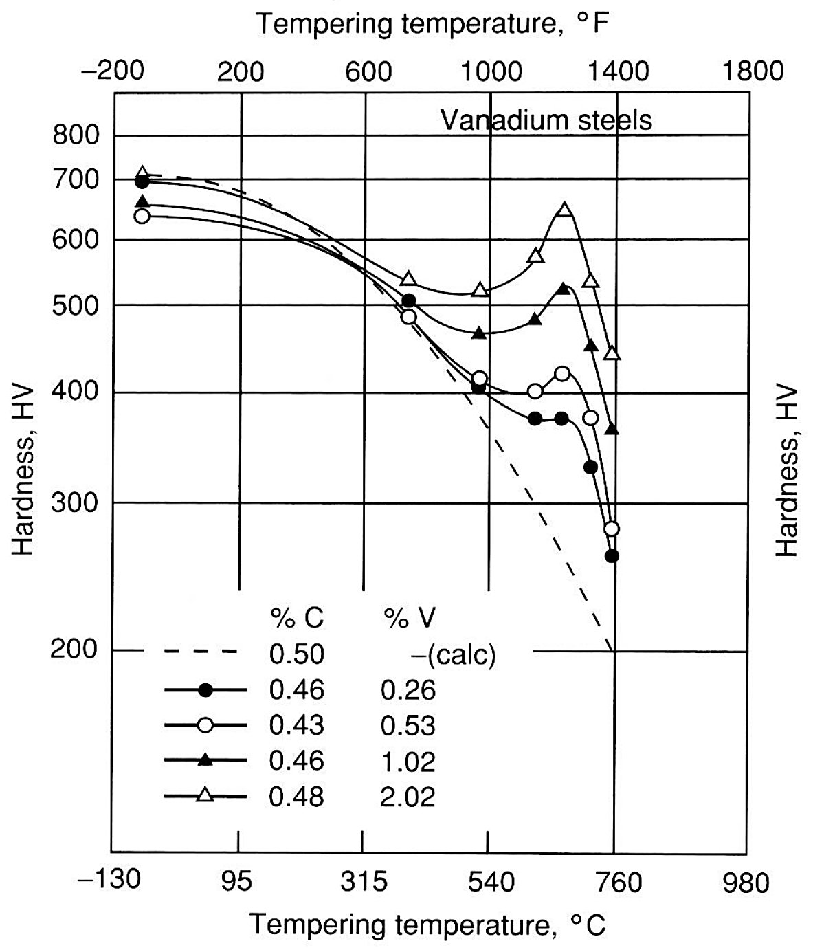
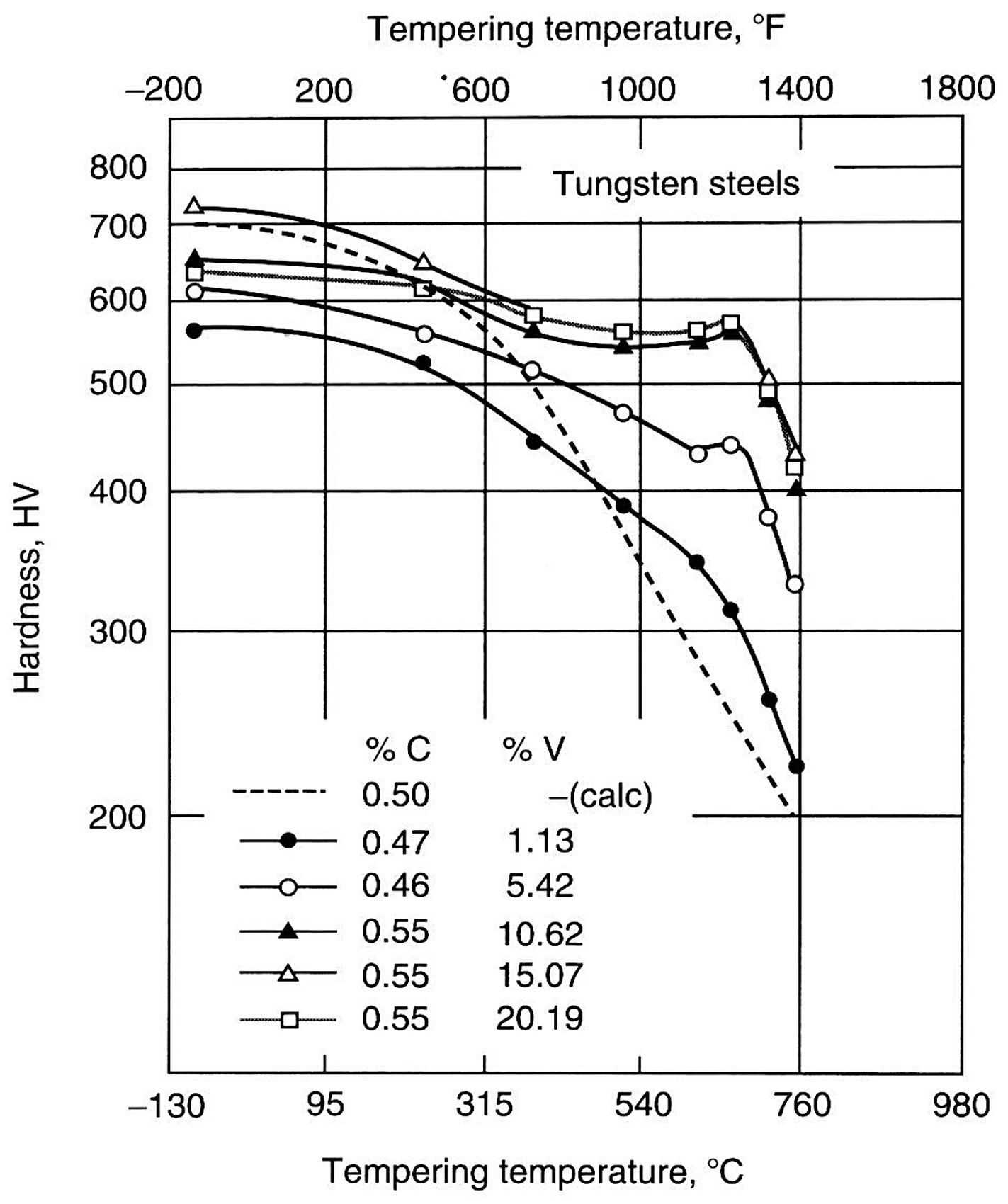
Tungsten produces the same peak from a different carbide, and the size of it depends on how much tungsten is in solution.
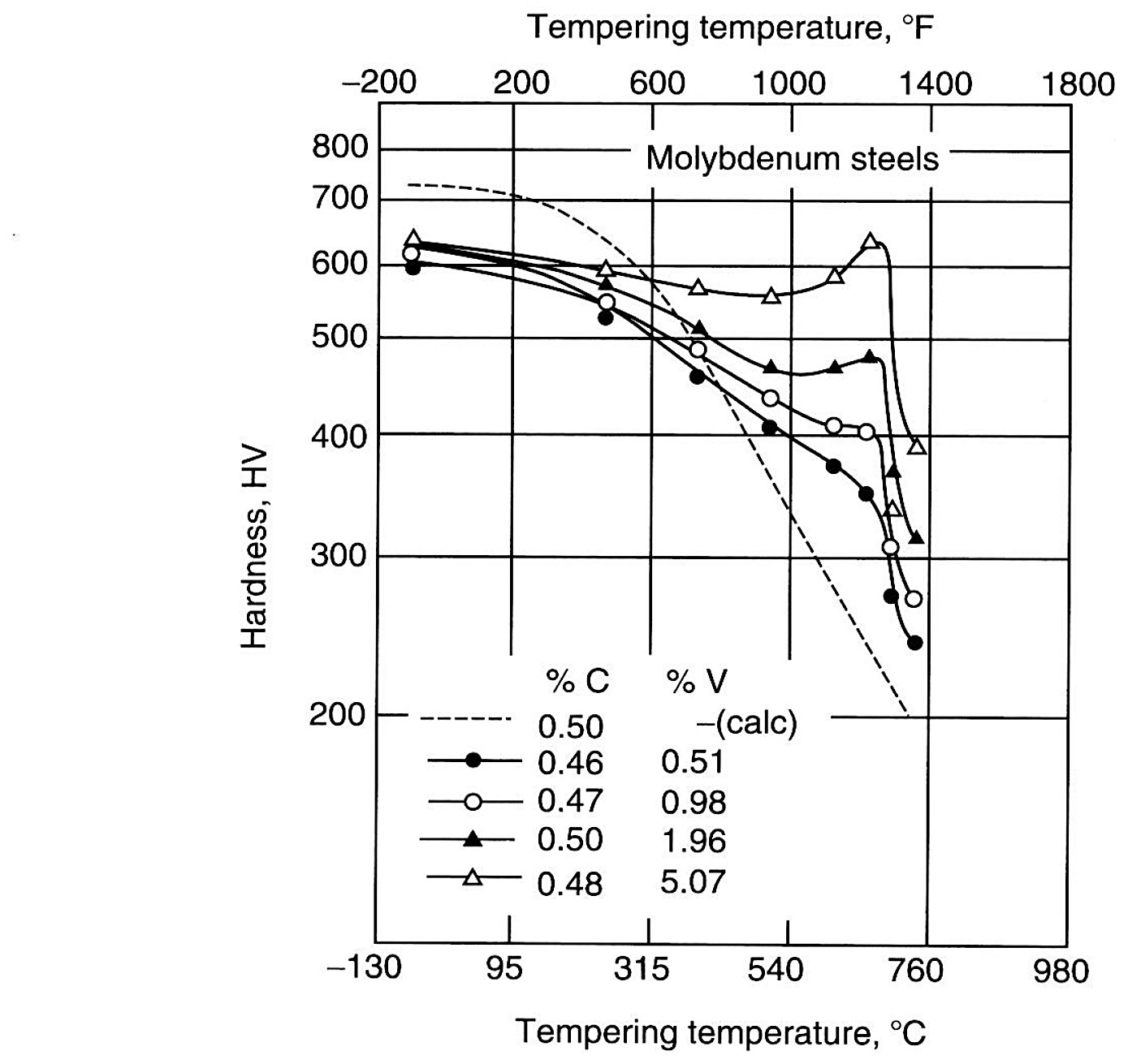
Molybdenum is the element most tool steel grades are built on, and it hardens on tempering at the levels these grades carry.
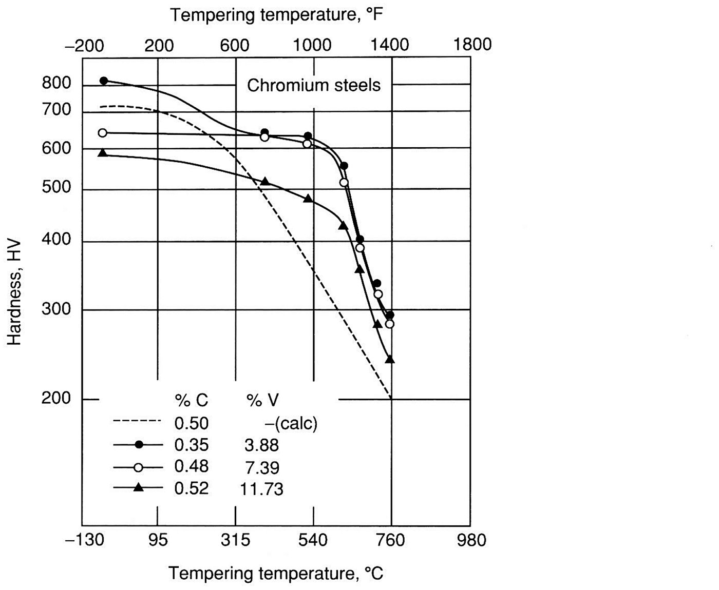
Chromium contributes to the same reaction, at the highest addition of the four carbide formers.
Retained austenite that was left in the structure
If retained austenite is present in an amount large enough to be seen under the light microscope, the steel was overaustenitized. Tempering will not convert a high level of retained austenite to martensite or bainite unless the tempering temperature is high enough, and the austenite that remains is not stable enough to survive the shock that a tool sees in service. When it does transform in service, the surrounding matrix is too hard and too low in ductility to absorb the transformation stress and the tool cracks. That is the reason the austenitizing temperature is held to the value where the grain is fine, which the austenitizing series on this site works through grade by grade.
What a quench that was too slow leaves behind
A structure that is not fully martensitic is the other defect a tool steel micrograph is checked for. It appears when the hardenability of the grade is not enough for the section size and the quench medium that were chosen, and the result is pearlite or bainite in the structure and a hardness under the figure on the drawing. Ferrite can also be present in the few hypoeutectoid grades. The brine and water hardening grades carry a second risk in the form of soft spots inside the case, caused by the tongs holding the part, which cool that patch of surface more slowly, or by agitation that is too weak to break up the vapor pockets formed by localized boiling of the quench medium.
A continuous-cooling diagram tells the same story with cooling curves instead of holds, and it is the one that matches a real quench. The diagram below carries the ferrite, pearlite, bainite and martensite fields of a eutectoid steel, with a set of cooling rates drawn across them.
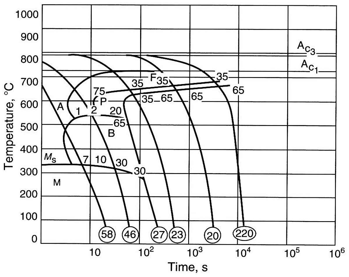
Isothermal transformation in a salt bath
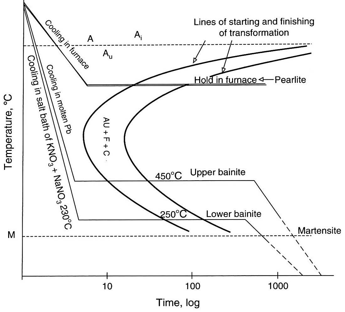
Holding a tool steel at a temperature above the martensite start and letting the transformation finish there produces pearlite or bainite rather than martensite, and the hold temperature picks which one. The four plates below are one shock resisting grade, S5, taken through that route at four temperatures. A hold in the pearlite range at 650 °C for 4 h gives ferrite and coarse pearlite at 23 to 24 HRC, and the same steel held at 595 °C for 8 h gives ferrite and fine pearlite at 36 HRC. Below the pearlite nose the product is bainite, upper bainite at 540 °C where the hold was stopped before the transformation finished, and lower bainite at 400 °C in 1 h, which is the harder and tougher of the two at 37 to 38 HRC.
The temperatures in that paragraph come off an isothermal transformation diagram. The one below is for a plain eutectoid carbon steel, but the shape is the one every tool steel follows: a pearlite nose at the top, a bainite bay below it, and the martensite start line across the bottom. Read a hold temperature off it and the product follows.
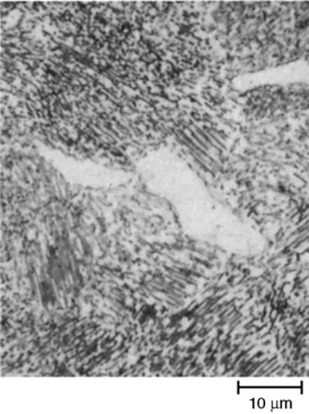
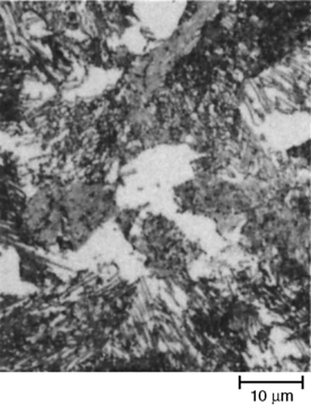
The transformation diagrams behind those holds are on the tool steel microstructure page for S7, together with the continuous cooling diagram that is read for a normal quench, and the hardness each grade holds after tempering is on the tempering chart.
Compiled from ASM Handbook, Volume 9, Metallography and Microstructures, article Metallographic Techniques for Tool Steels by George F. Vander Voort, ASM International, 2004 (tempering and isothermal transformation sections, Fig. 67 and Fig. 69 to Fig. 78). Every caption was read from the searchable text layer of the file and checked against the printed plate, and each plate was cropped from the file at 1.5 times its printed pixel width. The plates are a reference summary of published practice rather than an Aobo Steel specification, so confirm the tempering schedule and the hardness position against the material test certificate before a process sheet is written.