
Tool Steel Microstructure, Micrographs by Grade and Condition
A die that fails early usually failed at a carbide or at a grain boundary, and both of those are visible in a micrograph long before they show up as a cracked die. This page collects published micrographs of tool steels by grade and by condition, covering annealed bar, as-rolled and mill-annealed bar, hardened and tempered steel, nitrided cases and the cooling rate curves behind them, with the etchants and the preparation practice that produce each plate. Grades covered include W1, D2, D3, O1, A2, S7, H13, P20, M2 and M42.
What a tool steel micrograph has to show
Tool life is decided by three things that a micrograph has to show at the same time. The first is the carbide, its type, its size and how evenly it is distributed, because coarse or banded carbide is where a die cracks first. The second is the matrix, which is ferrite carrying spheroidal carbide in the annealed condition, plate or lath martensite with retained austenite after quenching, and tempered martensite with fine precipitated carbide after tempering. The third is the prior-austenite grain size, which appears as the network of boundaries in a hardened specimen and sets how much toughness is left after hardening.
The etchant decides which of the three is visible and the magnification decides how much of the structure fits in the frame. 2% nital is the default for hardened and tempered tool steel, 4% picral is the default for annealed and spheroidized steel, and Vilella’s reagent is the usual choice where the carbide has to be resolved at 1000x. The sections below are grouped by the condition the steel is in, because that is what decides which etchant and which magnification apply.
Tool steel in the annealed condition
Tool steel is delivered annealed so that it can be machined, and the anneal that matters is the spheroidize anneal. It takes the lamellar carbide of pearlite and balls it up into spheroids in a ferrite matrix, which brings the hardness down into the 170 to 240 HBW band and lets a die block be milled without chipping the edge. A grade that is annealed properly shows evenly sized spheroids spread through the ferrite. A grade whose cycle was cut short keeps lamellar pearlite in the structure, which raises hardness and tears the cutting edge.
The starting structure matters as much as the annealing cycle. W1 that was quenched to fine pearlite before the anneal spheroidizes into a more uniform carbide than the same steel annealed straight from the as-rolled condition, and the difference between the two is visible in the first plate below. The same section of the source also shows how the carbide in the water hardening, cold work, hot work and high speed families responds to the same anneal.
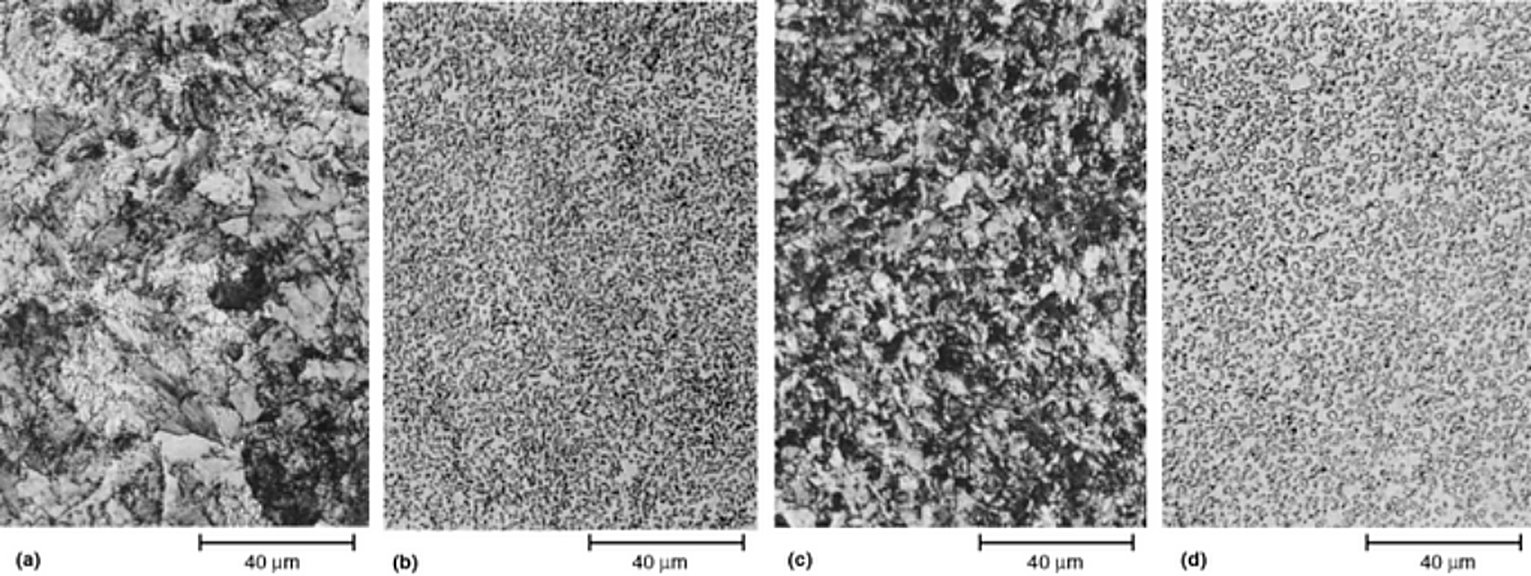
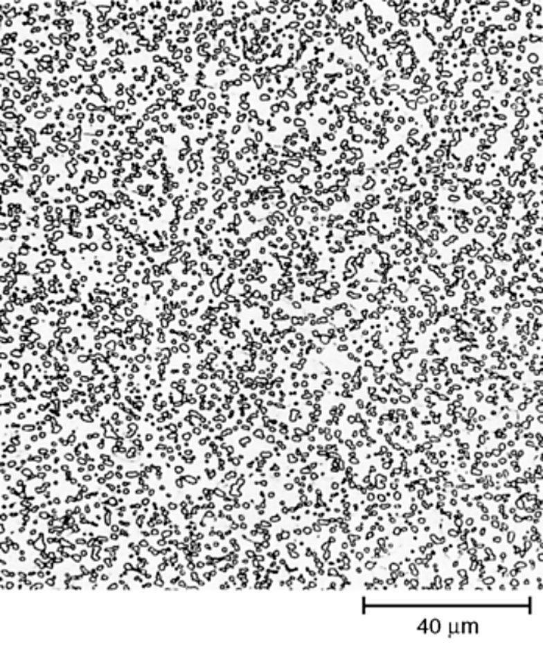
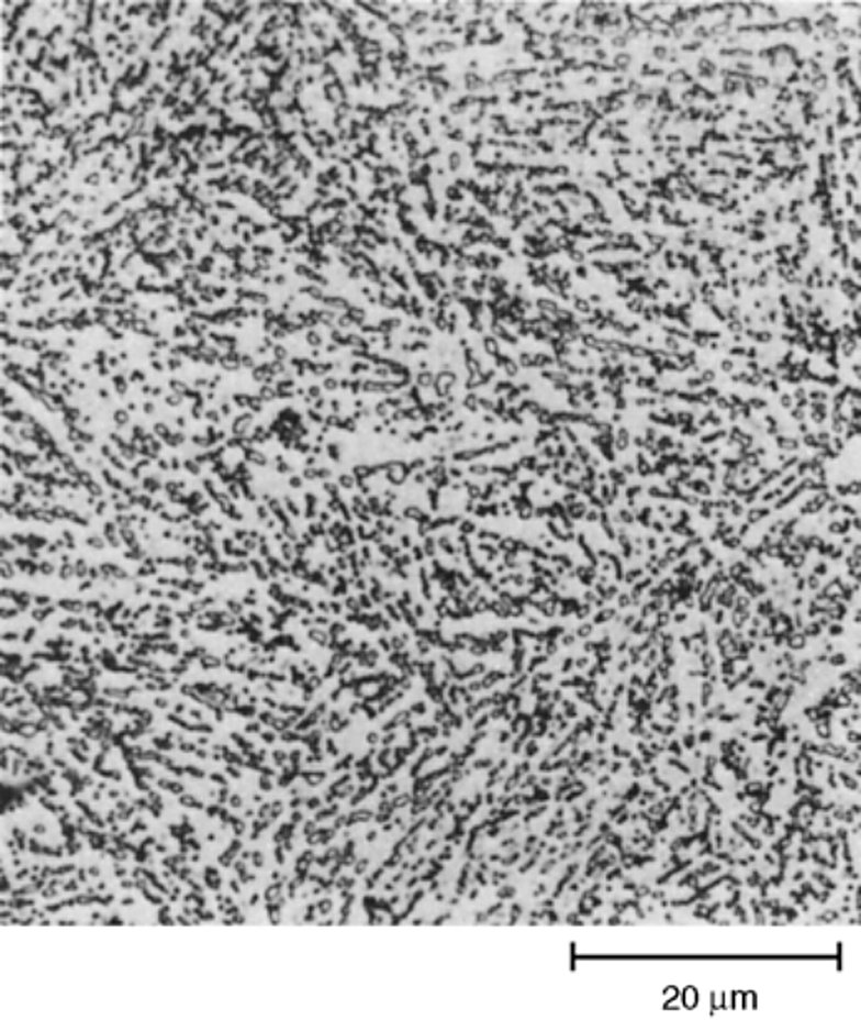
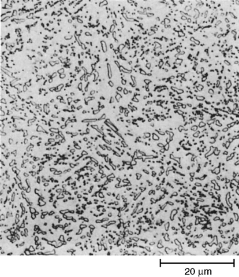
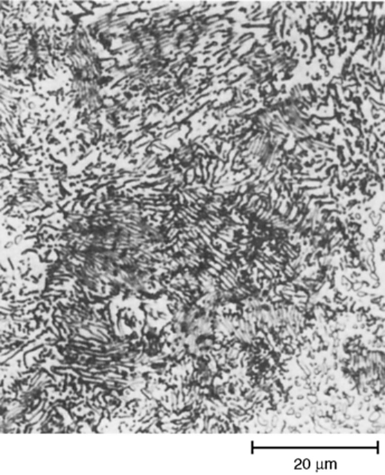
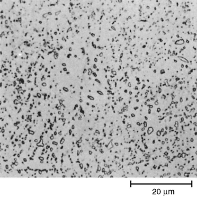
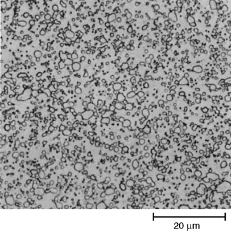
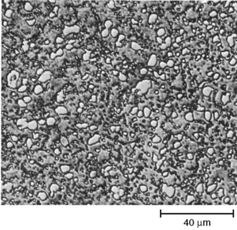
A comparison against these images is worth doing before a die block is machined, and the tool steel annealing and normalizing temperature chart gives the cycles that produce each of them.
As-rolled and mill-annealed bar
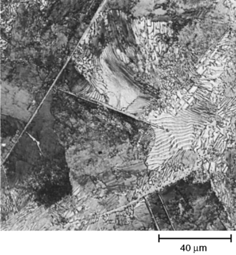
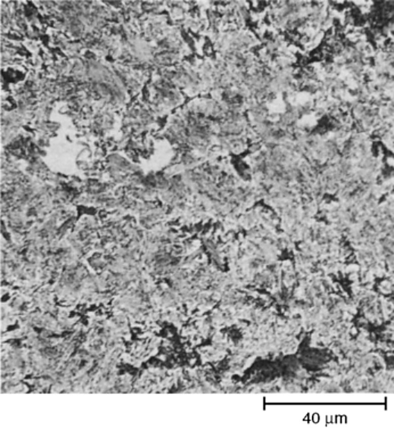
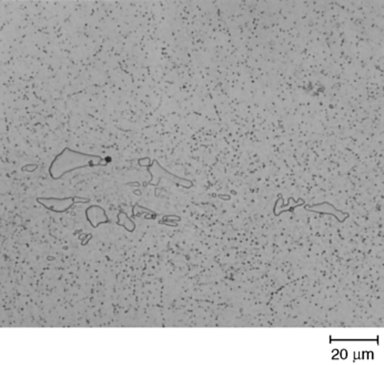
The structure of the bar as it arrives is the first item worth checking on incoming inspection, because it predicts how the steel will machine and how it will harden. Air hardening grades such as A2 and O1 can pick up bainite and martensite in the cooling line after rolling, which leaves the bar harder and more crack sensitive than the certificate hardness suggests. Highly alloyed grades band and segregate in the ingot, and the segregated bands carry a heavier carbide population than the rest of the section.
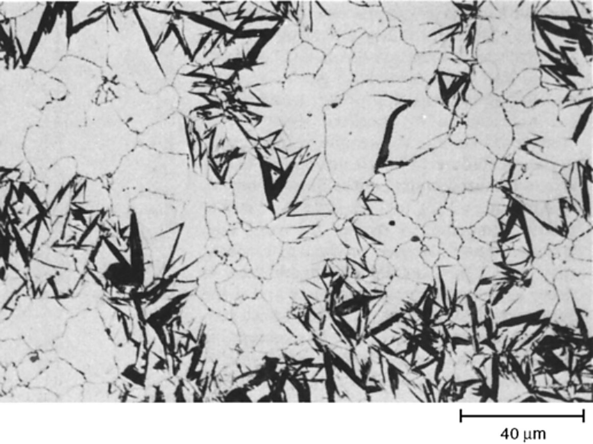
Grain boundary carbide networks are the other structure to look for. They form in type 420 stainless and in high carbon water hardening grades when the bar cools slowly through the carbide precipitation range after the last rolling pass, and they are still there after the anneal unless the piece was normalized first. Scattered grain boundary carbide is tolerable at low severity and becomes a cracking path at high severity.
Tool steel after hardening and tempering
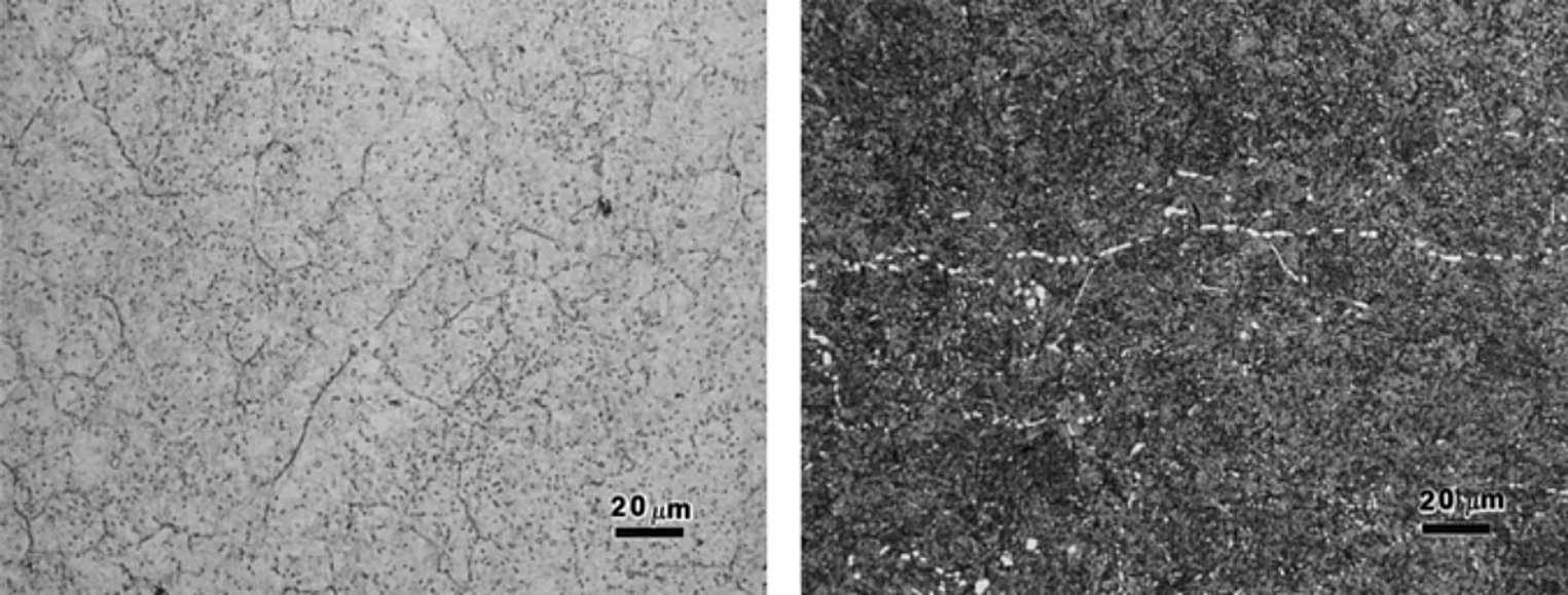
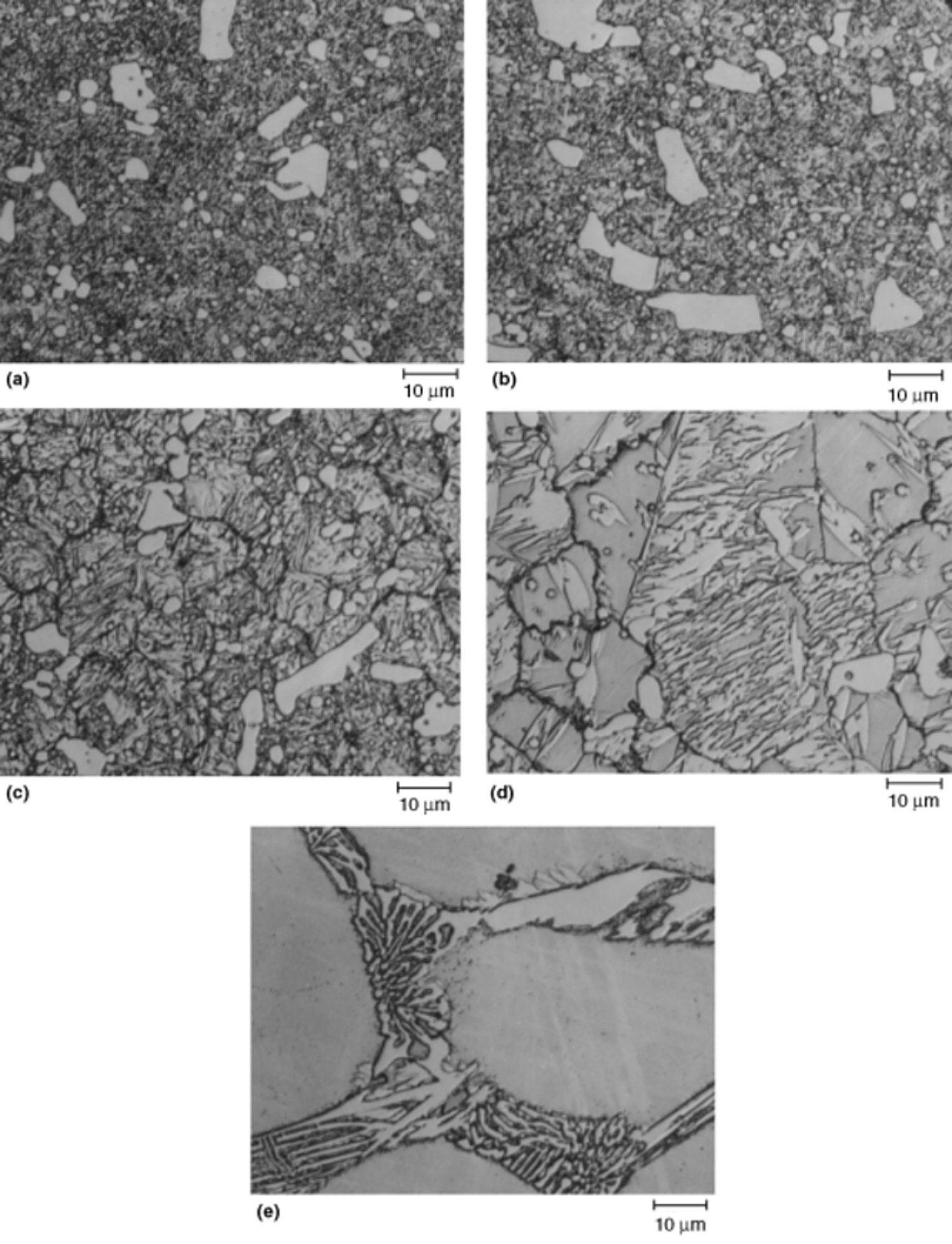
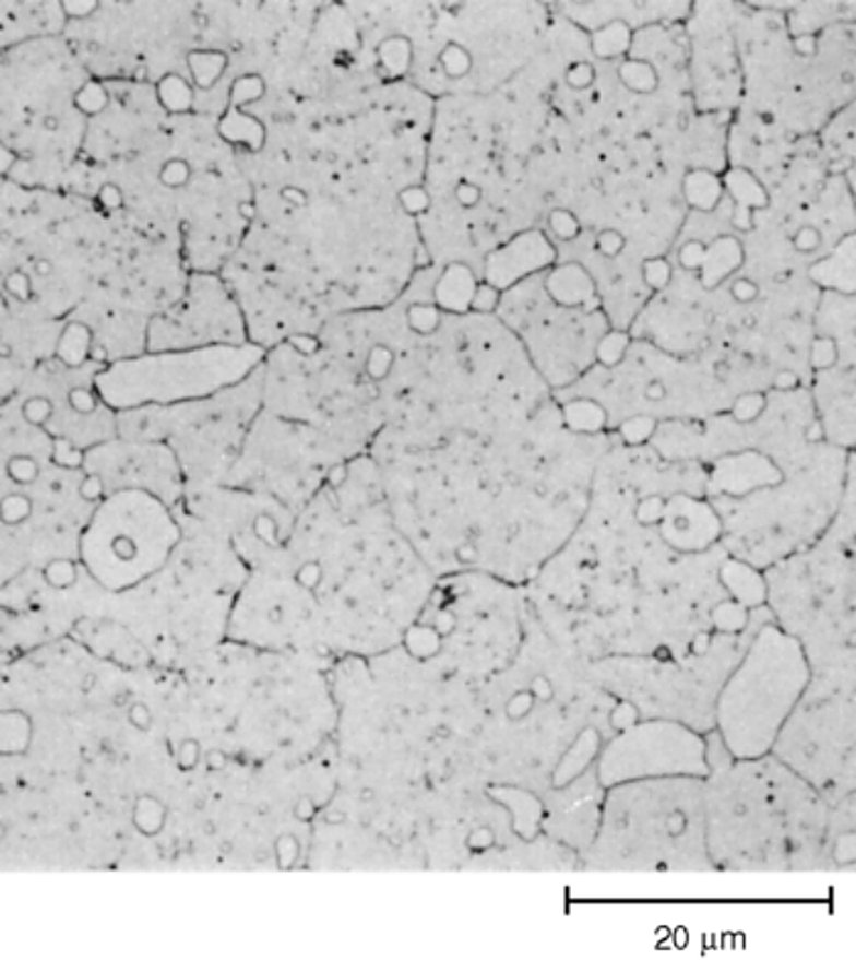
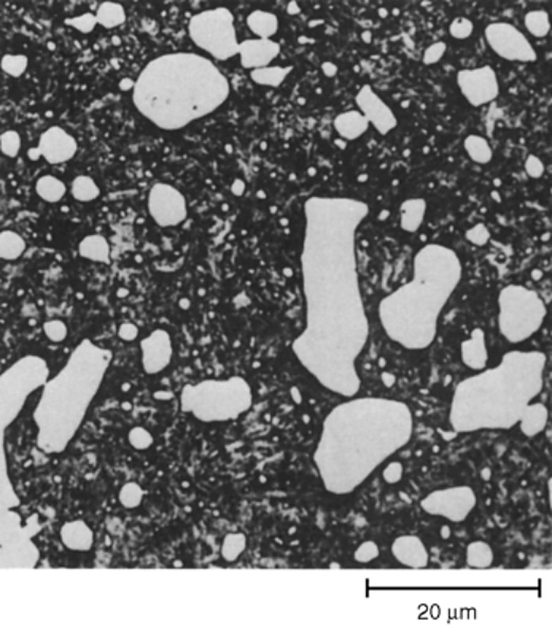
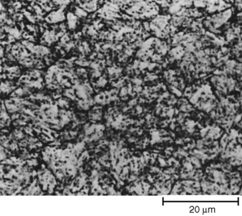
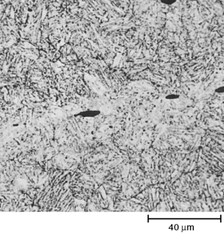
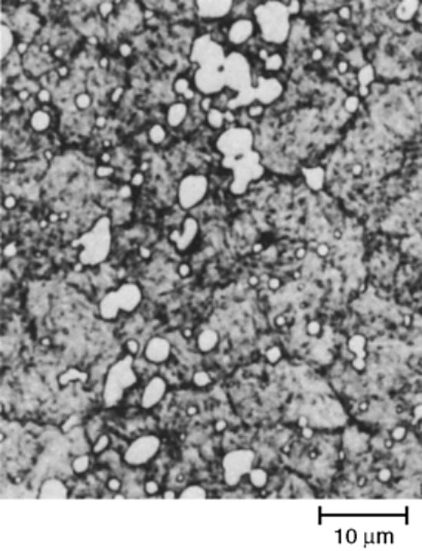
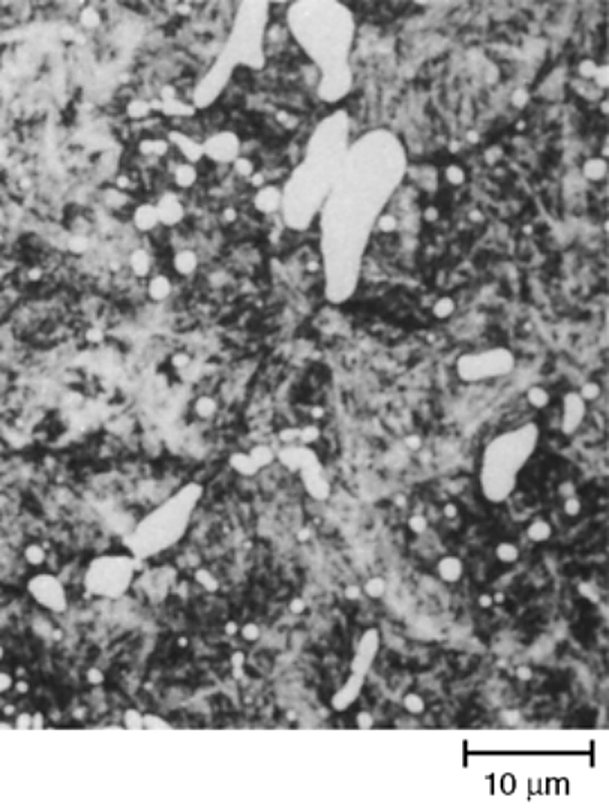
The hardened structure is what the die shop controls directly, and the micrographs below show the three things that change with the cycle. The first is how much undissolved carbide is left. D2 and D3 hold a substantial volume of it at any normal austenitizing temperature, which is where their wear resistance comes from, and a cold work die that has lost that carbide has been austenitized too hot. The second is retained austenite, which grows as the austenitizing temperature rises and cannot be seen under the light microscope until a substantial amount is present, so a sample that looks clean at 1010 °C and a sample taken from the same steel at 1230 °C have to be compared side by side. The third is the prior-austenite grain boundary network, which coarsens with austenitizing temperature and sets the toughness that remains.
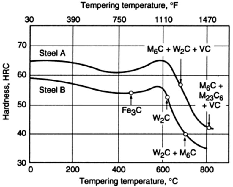
In the tempered condition the matrix is tempered martensite and the carbide that remains is the undissolved fraction plus whatever precipitated during the tempers. High speed steel holds its hardness through secondary hardening rather than through the as-quenched structure, which is why M2 is double tempered at 480 °C and M42 is triple tempered at 565 °C in the plates below. The hardness each of these grades reaches after each tempering temperature is set out on the tool steel tempering chart, and the hardness they keep when the die runs hot is on the hot hardness chart.

Cooling rate and the structure it produces
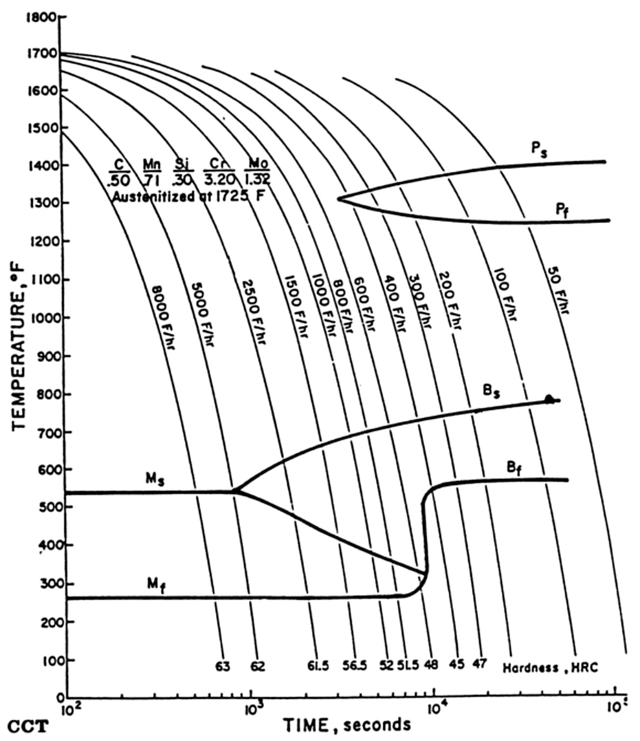
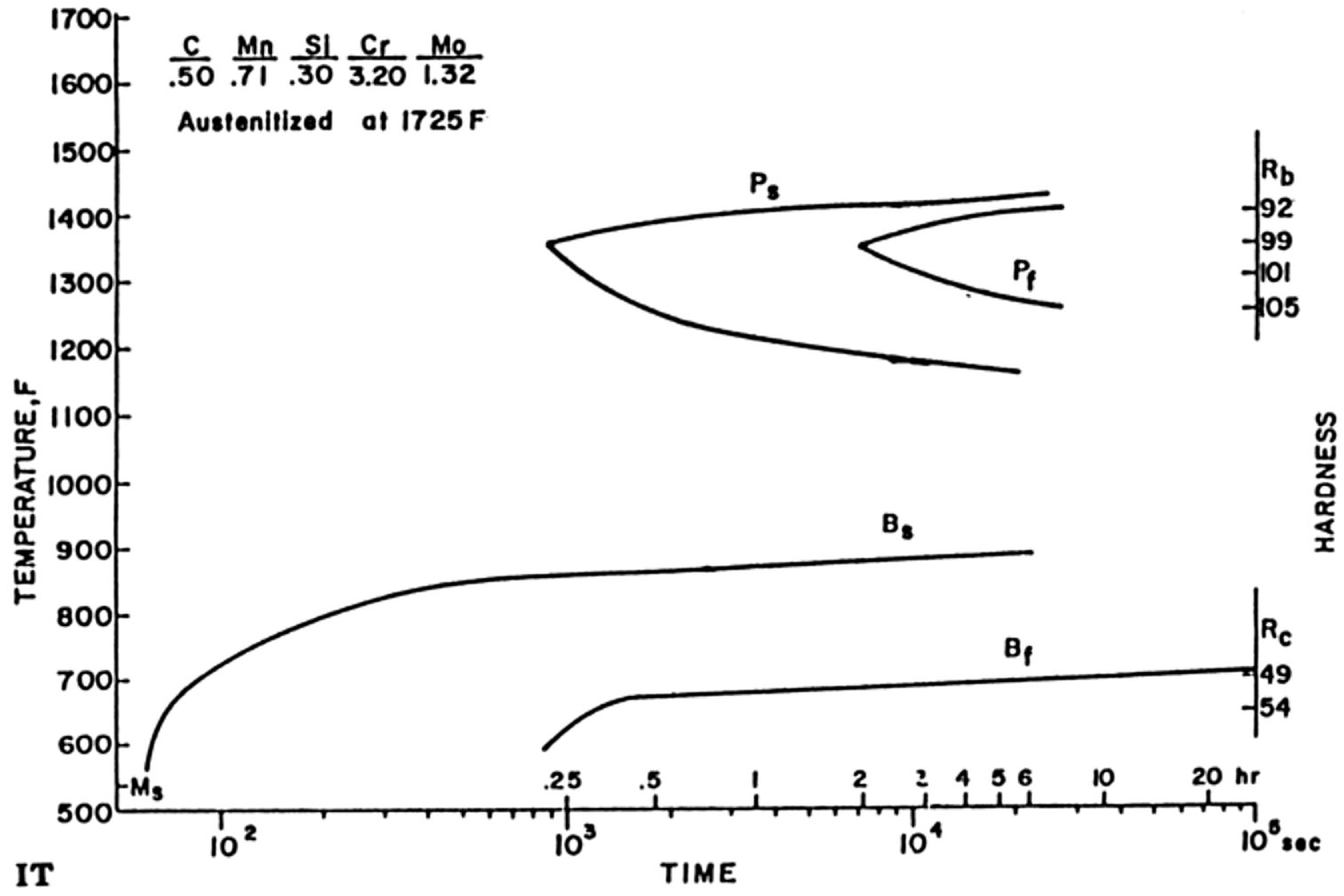
The transformation diagrams below belong to S7, a shock resisting grade whose hardenability sits between the water hardening and the air hardening families. The continuous cooling diagram gives the result for a die that is quenched in a specific medium, read across the hardness curve at the bottom, and the isothermal diagram gives the result for a die held at temperature in a salt bath. Both diagrams carry the same labels. Ms and Mf mark the start and finish of the martensite transformation, Bs and Bf the bainite start and finish, and Ps and Pf the pearlite start and finish.
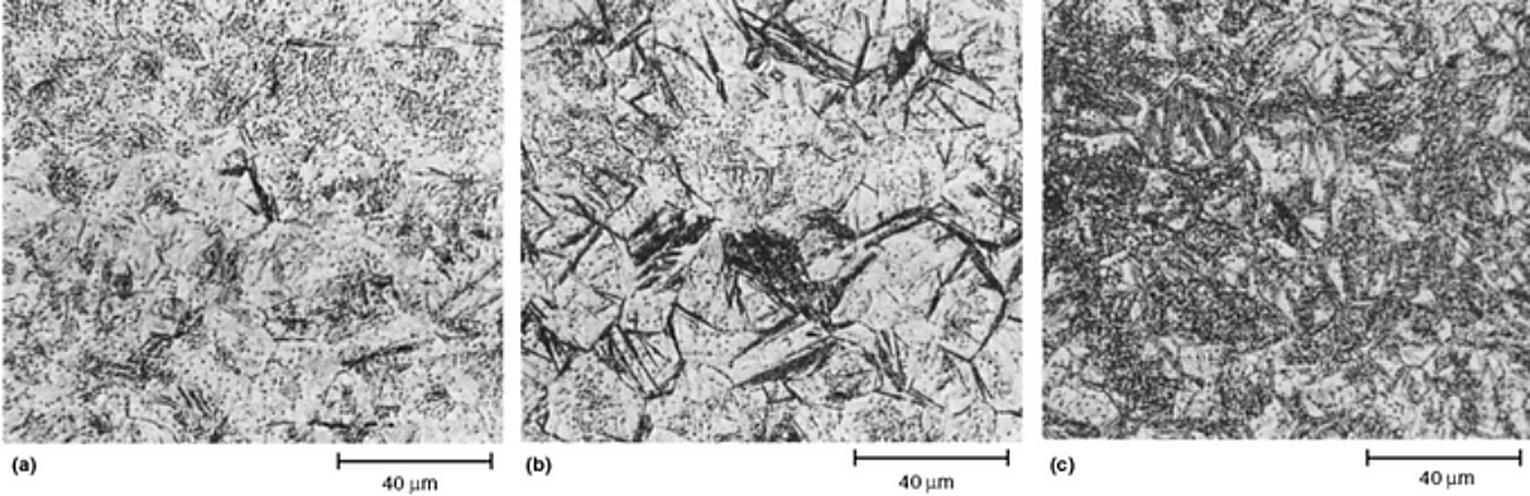
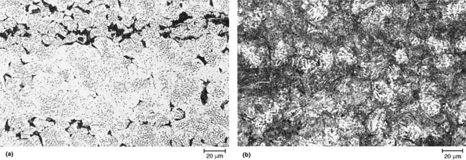
The micrographs below the diagram show what the curves predict. S7 austenitized at 940 °C and cooled at 2780 °C/h comes out as martensite with a small amount of bainite at 62 HRC, and the same steel cooled at 830 °C/h is mostly bainite at 56.5 HRC. An interrupted quench that holds the die at 704 °C long enough for the pearlite reaction to finish converts the structure to pearlite, which is the reason a salt bath hold time is chosen from the diagram rather than from a rule of thumb.
Which carbides the structure can hold
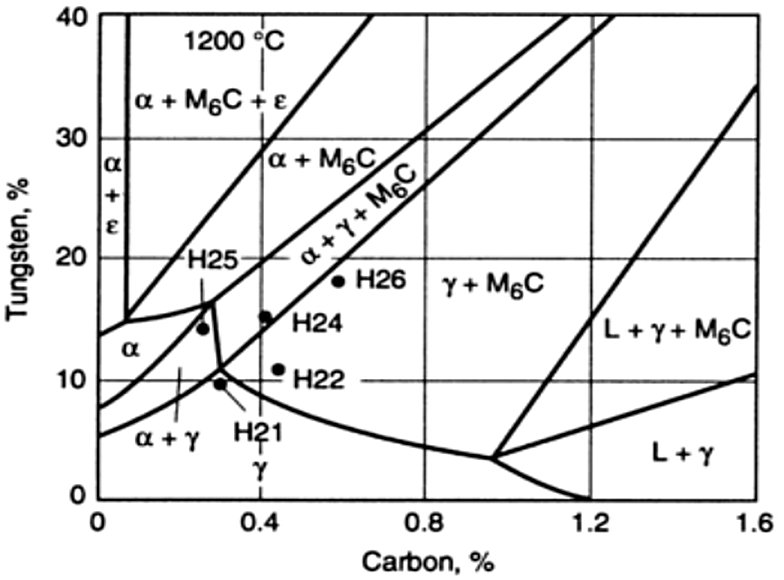
Carbide type is fixed by composition and by temperature rather than by heat treatment alone. The isothermal section of the Fe-Cr-C system shows where the chromium tool steels sit at 870 °C, with D2 and D3 in the field that holds M7C3 carbide and the hot work grades near the boundary between M7C3 and M23C6. That is the reason a 12% chromium cold work steel and a 5% chromium hot work steel behave differently above 500 °C even when both are tempered to the same room temperature hardness. In high speed steel the carbide sequence changes again as the tempering temperature rises, with M3C giving way to M2C and then to MC and M6C as the alloy carbides form.
Etchants and what each one reveals
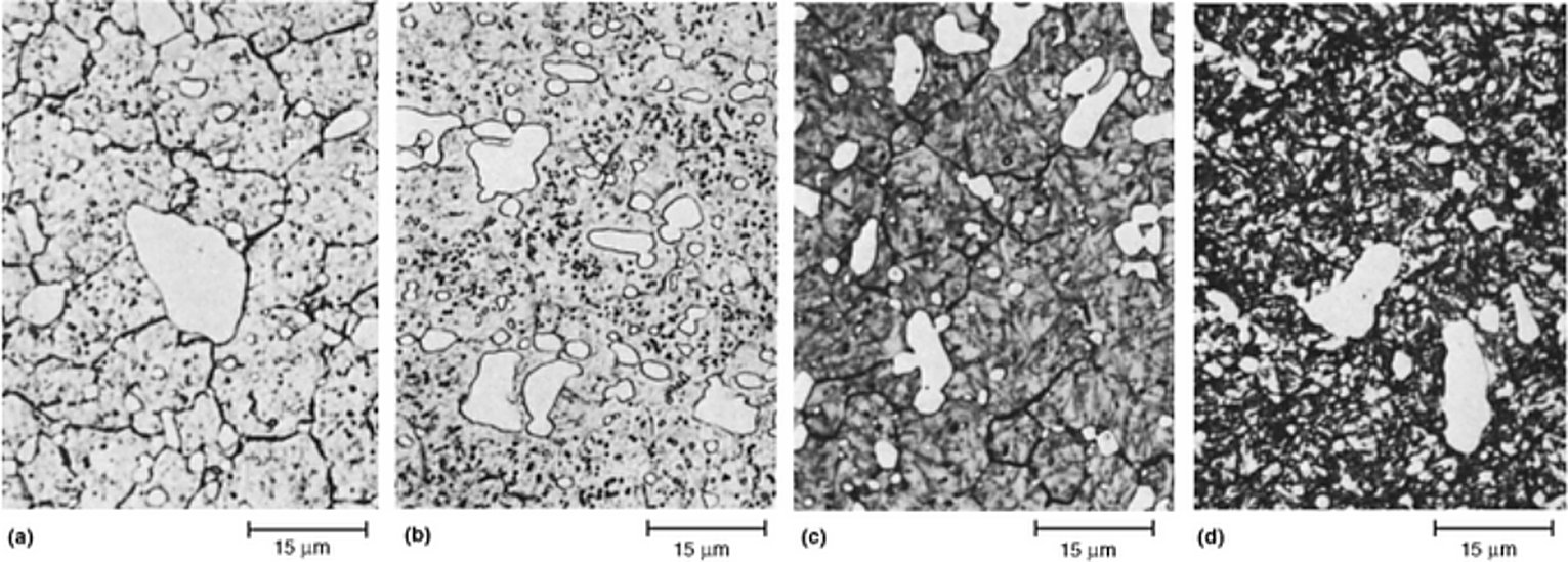
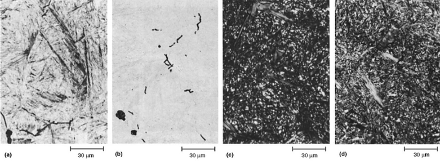
No single etchant shows everything in a tool steel. Nital outlines ferrite grain boundaries and the carbide interfaces in an annealed specimen and is the preferred reagent for martensite, picral is the better choice where pearlite or bainite has to be resolved, and the tint etch reagents color individual phases so that retained austenite or a specific carbide can be picked out. The table below lists the reagents printed for tool steel work with the comments that go with them, and the two plates underneath show the same specimen etched four different ways, which is the quickest way to see how much the choice of reagent changes the reading.
| Etchant | Comments |
|---|---|
| 1 to 10 mL HNO3 and 99 to 90 mL alcohol | Nital. The most commonly used etchant. Solutions with more than 3% HNO3 in ethanol are not stored. Reveals ferrite grain boundaries and ferrite-carbide interfaces in annealed steel and is the preferred etchant for martensite. Reveals prior-austenite grain boundaries in as-quenched and lightly tempered high alloy tool steels. 2 to 3% nital is most common and 5 to 10% nital is used for high alloy grades. Use by immersion. |
| 4 g picric acid and 100 mL ethanol | Picral. Recommended for annealed structures and for those containing pearlite or bainite. Does not reveal ferrite grain boundaries in annealed specimens. Etching response improves with 10 to 20 drops of zephiran chloride, and 1 to 5 mL HCl is added for high alloy grades. Use by immersion. |
| 1 g picric acid, 5 mL HCl and 100 mL ethanol | Vilella’s reagent. Used in the same manner as picral or picral plus HCl. |
| 10 g picric acid and 100 mL ethanol | Superpicral. Heated to dissolve the picric acid. Use by immersion for up to 1 min or more. A few drops of HCl raise the etch rate. |
| 2 g picric acid, 25 g NaOH and 100 mL H2O | Alkaline sodium picrate. Immerse in boiling solution for 1 to 15 min, or etch electrolytically at 6 V dc, 20 °C, for 30 to 120 s against a stainless steel cathode. Colors cementite and Fe4W2C. |
| 10 g K3Fe(CN)6, 10 g KOH or NaOH and 100 mL H2O | Murakami’s reagent. Fresh solution, hot or cold, for up to 10 min. Darkens chromium carbides and tungstides and does not attack martensite. |
| 1 g CrO3 and 100 mL H2O | Electrolytic etch at 2 to 3 V dc and 20 °C for 30 s against a stainless steel cathode. MC and M7C3 are darkened and Mo2C is outlined. |
| 10 mL H2O2 (30%) and 20 mL 10% aqueous NaOH | Immerse 10 s at 20 °C. Fe2MoC, Mo2C and M6C are outlined and the latter is also colored. |
| 4 g KMnO4, 4 g NaOH and 100 mL H2O | Groesbeck’s reagent. Immerse at 20 °C. Fe2MoC and M6C are outlined and colored blue and brown, Mo2C is colored brown, (Fe,Cr)23C6 is attacked and (Fe,Mo)23C is not attacked. |
| 4 g NaOH and 100 mL saturated aqueous KMnO4 | Immerse at 20 °C. Mo2C and M7C3 are attacked, M6C is outlined and colored brown. |
| Saturated aqueous picric acid plus a small amount of wetting agent | Prior-austenite grain boundary etch for hardened steels. Many wetting agents can be used, most commonly sodium tridecylbenzene sulfonate. Use at 20 to 100 °C for 2 to 60 min. About 1% HCl is useful for higher alloy grades. Room temperature etching in a beaker in an ultrasonic cleaner works well, and light backpolishing removes surface smut. |
| 50 mL cold saturated aqueous Na2S2O3, 1 g K2S2O5 | Klemm’s reagent, a tint etch. Immerse and never swab, at 20 °C for 40 to 100 s, to color ferrite blue or red and martensite brown. Cementite and austenite are unaffected. |
| 1 g Na2MoO4 and 100 mL H2O | Beraha’s tint etch for cementite. Add 0.2 to 0.3 g NH4-HF, then HNO3 to a pH of 2.5 to 3.0. Pre-etch with picral. Colors Fe3C yellow-orange. Immerse for up to 60 s and never swab. |
| 3 g K2S2O5, 10 g anhydrous Na2S2O3 and 100 mL H2O | Beraha’s tint etch. Immerse and never swab until the surface is colored red-violet. Colors ferrite, martensite, bainite and pearlite. Cementite is unaffected. |
Source, ASM Handbook, Vol 9, Metallographic Techniques for Tool Steels, Table 4, microstructural etchants for tool steels. When water is specified, distilled water is meant.
Nitrided cases on hot work die steel
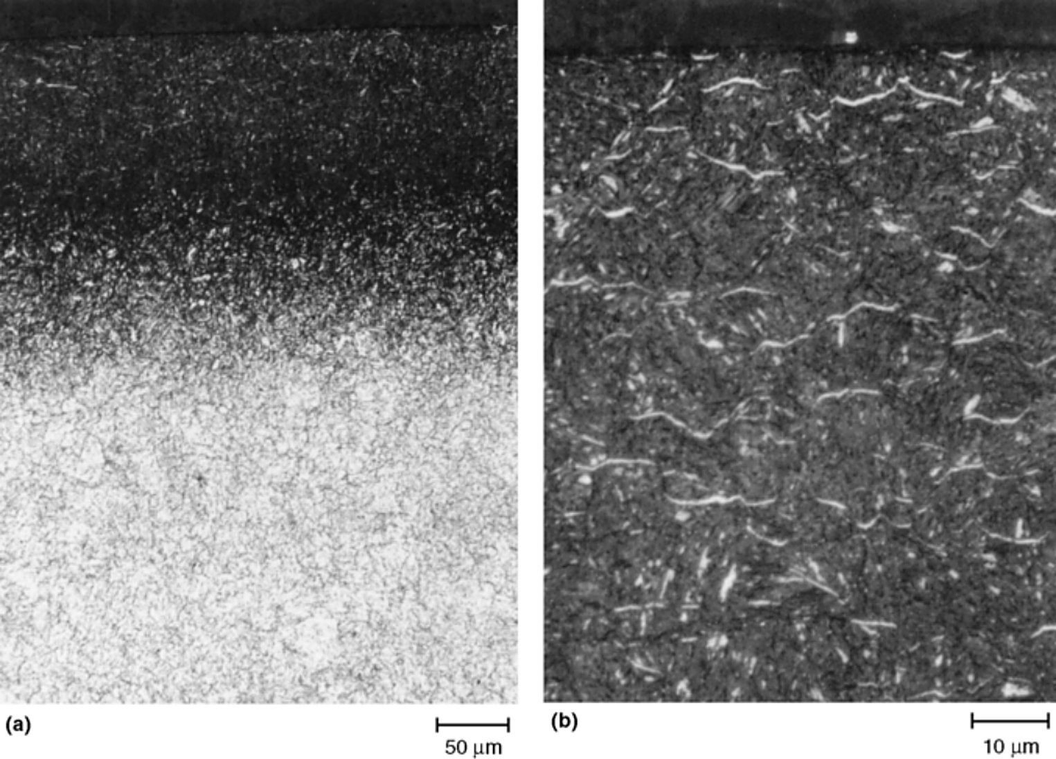
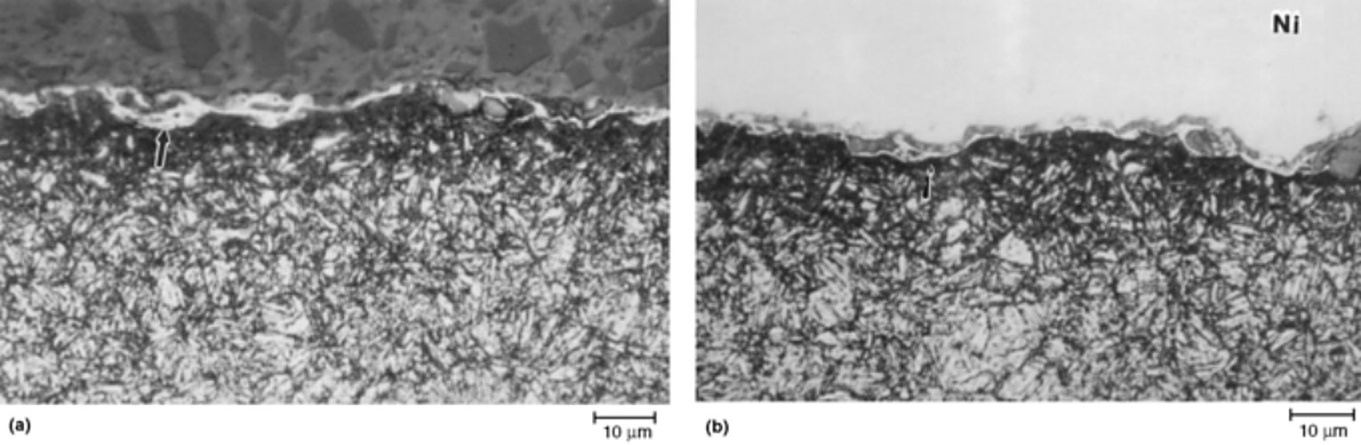
A nitrided case adds wear resistance to a hot work die without a further quench, and the case has to be read in the micrograph before the die is put into service. The compound layer at the extreme surface is the brittle part, and a white etching iron nitride layer at the surface is what a die shop looks for when it decides how much of the case has to be removed before the die runs. Mounting and edge retention decide whether that layer survives preparation at all. In the second plate below the same nitrided specimen is mounted with and without nickel plating, and the plated sample is the one in which the layer can be measured.
Specimen preparation practice for tool steels
Tool steel is harder and more highly alloyed than carbon steel, so it is prepared with more diamond and less abrasive paper than a structural steel specimen. The three practices below are the contemporary five step, four step and three step routes printed for tool steel, and all three use a single silicon carbide or rigid disk grinding step followed by diamond polishing and a final colloidal silica stage. Comp means complementary rotation, with the head and the base turning in the same direction, and Contra means the head turns against the base, which cuts faster and is used for the final stage.
Five step practice
| Surface | Abrasive/size | Load, N | Load, lbf | Speed, rpm/direction | Time, min |
|---|---|---|---|---|---|
| Waterproof grinding paper (or equivalent) | 120/P120 to 240/P280 grit SiC, water cooled | 22-27 | 5-6 | Comp | Until plane |
| Silk cloth or rigid grinding disk | 9 µm diamond, with lubricant | 22-27 | 5-6 | Comp | 5 |
| Woven (napless) or pressed cloths | 3 µm diamond, with lubricant | 22-27 | 5-6 | Comp | 3 |
| Woven or pressed cloths | 1 µm diamond, with lubricant | 22-27 | 5-6 | Comp | 2 |
| Medium-nap cloth | About 0.05 µm colloidal silica or sol-gel type alumina suspension | 22-27 | 5-6 | Contra | 1.5-2 |
Source, ASM Handbook, Vol 9, Metallography and Microstructures, Metallographic Techniques for Tool Steels (G.F. Vander Voort), Table 1, five step preparation practice for tool steels.
Four step practice, with a rigid grinding disk
| Surface | Abrasive/size | Load, N | Load, lbf | Speed, rpm/direction | Time, min |
|---|---|---|---|---|---|
| Waterproof grinding paper (or equivalent) | 120/P120 to 240/P280 grit SiC, water cooled | 27 | 6 | 240-300, Comp | Until plane |
| Rigid grinding disk (or woven cloth) | 9 µm diamond suspension, with lubricant | 27 | 6 | 120-150, Comp | 5 |
| Woven (napless) or pressed cloths | 3 µm diamond, with lubricant | 27 | 6 | 120-150, Comp | 3 |
| Medium-nap cloth | About 0.05 µm colloidal silica or sol-gel type alumina suspension | 27 | 6 | 120-150, Contra | 2 |
Source, ASM Handbook, Vol 9, Metallography and Microstructures, Metallographic Techniques for Tool Steels (G.F. Vander Voort), Table 2, four step preparation practice for tool steels.
Three step practice
| Surface | Abrasive/size | Load, N | Load, lbf | Speed, rpm/direction | Time, min |
|---|---|---|---|---|---|
| Waterproof paper (or equivalent) | 120/P120 to 320/P400 grit SiC, water cooled | 27 | 6 | 240-300, Comp | Until plane |
| Hard or soft rigid grinding disks | 3 µm diamond suspension | 27 | 6 | 120-150, Comp | 5 |
| Medium-nap cloth | About 0.05 µm colloidal silica or sol-gel type alumina suspension | 27 | 6 | 120-150, Contra | 5 |
Source, ASM Handbook, Vol 9, Metallography and Microstructures, Metallographic Techniques for Tool Steels (G.F. Vander Voort), Table 3, three step preparation practice for tool steels.
Nominal compositions of the grades shown
The compositions below are the nominal values printed for the grades illustrated on this page, so that a reader can see what separates the families. Carbon and chromium do most of the work in the cold work grades, tungsten and molybdenum carry red hardness in the high speed grades, and the hot work grades sit in the middle of the chromium range with molybdenum for temper resistance.
| AISI type | C | Mn (a) | Si (b) | Cr | Ni | V | W | Mo | Co | Ti | |
|---|---|---|---|---|---|---|---|---|---|---|---|
| W1 | 0.6-1.4 | … | … | … | … | 0.25 | … | … | … | … | |
| W2 | 0.6-1.4 | … | … | … | … | … | … | … | … | … | |
| S1 | 0.5 | … | 0.75 | 1.5 | … | 0.2 (c) | 2.5 | … | … | … | |
| S2 | 0.5 | 0.4 | 1.0 | … | … | … | … | 0.5 | … | … | |
| S4 | 0.55 | 0.8 | 2.0 | … | … | … | … | … | … | … | |
| S5 | 0.55 | 0.8 | 1.9 | 0.25 (c) | … | 0.2 (c) | … | 0.4 | … | … | |
| S7 | 0.5 | 0.7 | … | 3.25 | … | … | … | 1.40 | … | … | |
| O1 | 0.9 | 1.0 | … | 0.5 | … | 0.2 (c) | 0.5 | … | … | … | |
| O2 | 0.9 | 1.6 | … | … | … | … | … | … | … | … | |
| O6 | 1.45 | 0.8 | 1.1 | … | … | … | … | 0.25 | … | … | |
| A2 | 1.0 | 0.7 | … | 5.25 | … | 0.2 (c) | … | 1.1 | … | … | |
| A6 | 0.7 | 2.0 | … | 1.0 | … | … | … | 1.35 | … | … | |
| A7 | 2.00-2.85 | 0.8 | 0.5 | 5.0-5.75 | 0.3 | 3.9-5.15 | 0.5-1.5 | 0.90-1.40 | … | … | |
| A10 | 1.25-1.50 | 1.6-2.1 | 1.0-1.5 | … | … | 1.55-2.05 | … | 1.25-1.75 | … | … | |
| D2 | 1.5 | 0.5 | … | 12.0 | … | 0.2-0.9 (c) | … | 0.8 | … | … | |
| D3 | 2.1 | … | … | 12.0 | 0.5 (c) | … | … | … | … | … | |
| H11 | 0.35 | … | 0.9 | 5.0 | … | 0.4 | … | 1.5 | … | … | |
| H13 | 0.35 | … | 1.0 | 5.25 | … | 1.0 | … | 1.3 | … | … | |
| H21 | 0.35 | … | … | 3.5 | … | 0.4 (c) | 9.0 | … | … | … | |
| H23 | 0.25-0.35 | 0.15-0.40 | 0.15-0.60 | 11.0-12.75 | … | 0.75-1.25 | 11.0-12.75 | … | … | … | |
| H26 | 0.45-0.55 | 0.15-0.40 | 0.15-0.40 | 3.75-4.5 | 0.3 | 0.75-1.25 | 17.25-19.0 | … | … | … | |
| T1 | 0.7 | … | … | 4.0 | … | 1.0 | 18.0 | … | … | … | |
| T15 | 1.5 | … | … | 4.0 | … | 5.0 | 12.0 | … | 5.0 | … | |
| M1 | 0.8 | … | … | 4.0 | … | 1.1 | 1.5 | 8.5 | … | … | |
| M2 | 0.85 | … | … | 4.0 | … | 2.0 | 6.0 | 5.0 | … | … | |
| M4 | 1.3 | … | … | 4.5 | … | 4.0 | 5.5 | 4.5 | … | … | |
| M42 | 1.1 | … | … | 3.75 | … | 1.15 | 1.5 | 9.5 | 8.0 | … | |
| L1 | 1.0 | … | … | 1.4 | … | … | … | … | … | … | |
| L6 | 0.75 | 0.75 | … | 0.9 | 1.75 | … | … | 0.35 | … | … | |
| F2 | 1.25 | 0.75 | … | … | … | … | 0.35 | … | … | … | |
| P5 | 0.1 | … | … | 2.25 | … | … | … | … | … | … | |
| P20 | 0.35 | … | … | 1.25 | … | … | … | 0.4 | … | … | |
| AHT | 1.0 | … | … | 3.0 | … | … | 0.25 | 1.05 | 1.1 | … | 1.0 |
Source, ASM Handbook, Vol 9, Metallographic Techniques for Tool Steels, Table 5, nominal compositions of illustrated tool steel grades. (a) All tool steels contain some manganese, generally 0.2 to 0.4% when not listed. (b) Tool steels usually contain 0.2 to 0.35% Si unless listed otherwise. (c) Optional addition at the discretion of the manufacturer. A three dot entry means the element is not listed for that grade.
Composition data is for general reference only. Actual values vary by standard, mill, and heat number. Confirm against the material test certificate or contact Aobo Steel.
Where these structures are checked in practice
A die shop that wants a second opinion on a structure can compare its own specimen against the plates on this page and against the structures published for tool steel carbide types, for the carbide volume fraction of each grade and for H13 after quenching. The grade pages linked from the introduction above carry the composition, the heat treatment schedule and the properties for each of the grades shown here.
Compiled from ASM Handbook, Volume 9, Metallography and Microstructures, article Metallographic Techniques for Tool Steels by George F. Vander Voort, ASM International, 2004 (Tables 1 to 5 and plates Fig. 7 to Fig. 82). Every caption was read from the searchable text layer of the file and checked against the printed plate, and each plate was cropped from the file at 1.5 times its printed pixel width. The tables and micrographs are a reference summary of published practice rather than an Aobo Steel specification, so confirm the grade and the heat treatment condition against the material test certificate before a process sheet is written.