
P/M Tool Steel Properties, Carbide Size, Wear and Toughness
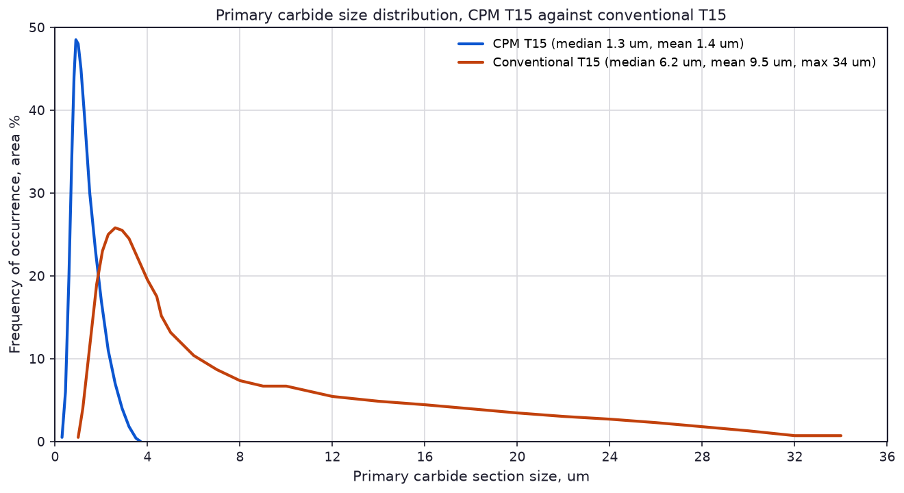
Powder metallurgy tool steel is bought for one reason. The carbides in it are small and evenly spread instead of coarse and banded. Everything else about the grade follows from that, and the charts on this page measure it. The median primary carbide in CPM T15 is 1.3 µm against 6.2 µm in the conventional steel of the same grade, and the wear test that follows from it puts a vanadium P/M grade an order of magnitude ahead of D2. This page collects the carbide size distribution, the microstructures, the crossed-cylinder wear data, the Charpy impact data and the grindability ratios for the P/M tool steels and their conventional counterparts.
What the powder route changes
A conventional tool steel is melted and cast, so the carbides form during solidification and the last liquid to freeze is rich in carbon and alloy. That produces carbide bands, and it produces a carbide population with a long tail of large particles. In the P/M route the melt is gas atomized into powder, each particle solidifies on its own, and the powder is then consolidated by hot isostatic pressing, extrusion or forging. Carbide segregation can only happen inside a particle a few tens of microns across, so after consolidation the structure is uniform at the scale of the part rather than at the scale of the ingot.
The measurement that says all of this in one line is the primary carbide size distribution below. The CPM T15 curve is a narrow peak, median 1.3 µm and mean 1.4 µm. The conventional T15 curve peaks later and drags a tail out to a maximum of 34 µm. A 34 µm carbide is a crack initiation site in a tool edge, and it is the particle that chips out first.
The structure that goes with it
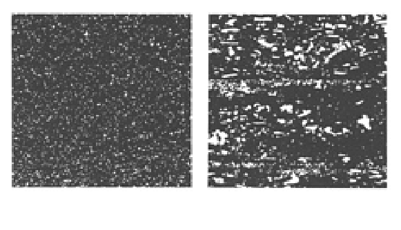
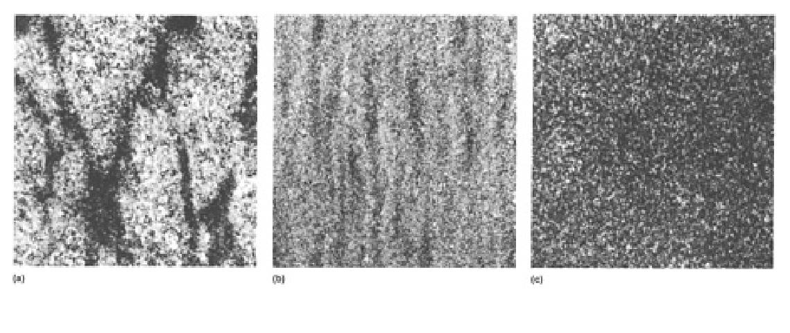
The micrographs below are the same two grades at the same magnification. In CPM T15 the carbides are a fine, even field; in conventional T15 they are coarse and arranged in bands, which is the structure left by segregation. The third figure does the same comparison on a die steel rather than a cutting tool, and it separates the two conventional routes from the powder one. Standard conventional H13 is coarse and heavily banded; premium-quality conventional H13, which is made to tighter segregation limits, is finer but still banded; P/M H13 is even, with no bands at all. The hot work grade is where the difference shows up as thermal fatigue resistance rather than edge chipping, because the crack that starts at a carbide band runs a little further every cycle.
Wear resistance in the crossed-cylinder test
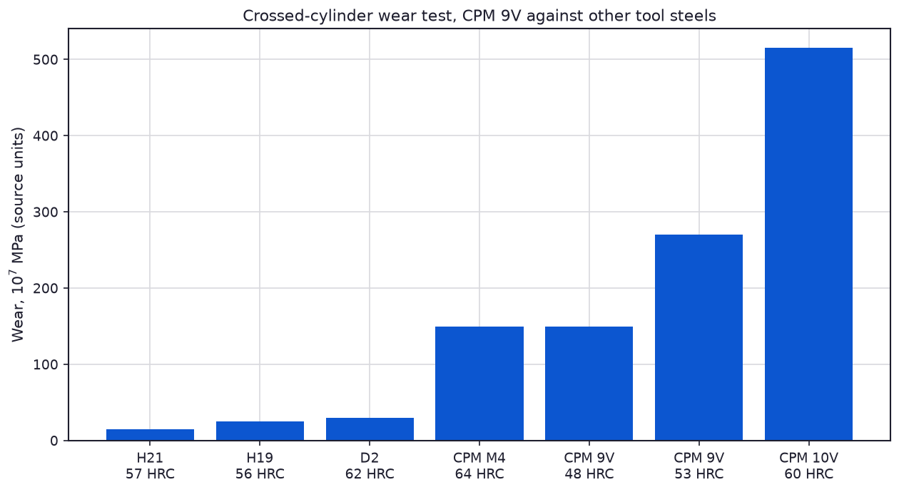
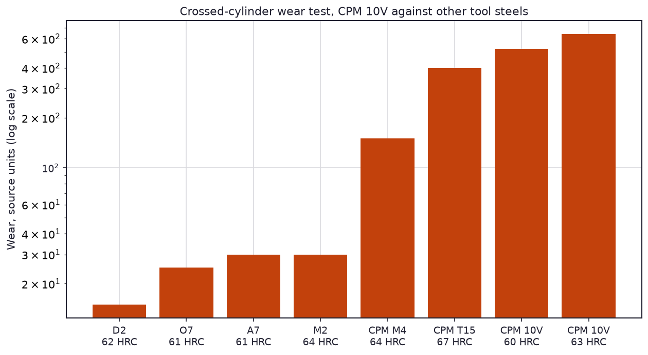
The crossed-cylinder wear test presses two cylinders against each other under load and measures the volume lost, and it is the test the tool steel industry quotes for abrasive wear. Read the two charts together. The conventional grades sit at the bottom of the scale, H21 at 15, H19 at 25 and D2 at 30 in the first chart, and D2 about 15, O7 about 25, A7 and M2 about 30 in the second. The P/M grades separate from them by an order of magnitude, and the separation grows with vanadium content, CPM M4 at 150, CPM 9V at 150 and 270 at two hardness levels, CPM T15 about 400, and CPM 10V 515 at 60 HRC in the first chart and about 520 and 640 in the second. CPM 10V is the high-vanadium cold work grade, and this test is the reason it is specified for long-run blanking and for wear parts that were previously made in carbide.
Impact toughness in the same grades
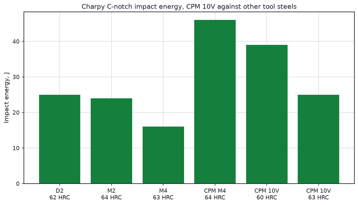
Fine carbides help toughness as well as wear resistance, because the coarse particle is what starts the crack. In the Charpy C-notch data below, CPM M4 reaches 46 J at 64 HRC while conventional M4 is at 16 J at 63 HRC, and CPM 10V sits at 39 J at 60 HRC. The exception is worth reading carefully. The same CPM 10V taken up to 63 HRC comes back at 25 J, so the toughness advantage is bought back by hardness in the most highly alloyed grade on the page. That is the normal trade, and it is why the P/M grades are ordered at the hardness the job needs rather than at the hardest the grade can reach.
Grindability
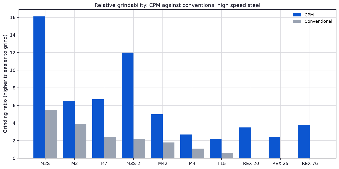
The last chart is the one that decides the shop cost. The grinding ratio is the volume of metal removed divided by the volume of wheel worn, so a higher number means the steel grinds easier. Every CPM grade beats its conventional equivalent, M2S 16.1 against 5.5, M3S-2 12.0 against 2.2, M42 5.0 against 1.8, T15 2.2 against 0.6. A P/M tool steel is more expensive per kilogram and cheaper to finish, and on a complex tool the grinding time is often the larger number of the two.
When to specify the powder route
The P/M grades earn their price where the failure mode is carbide related, edge chipping on a high-vanadium tool, banded wear on a long-run blanking die, thermal fatigue cracking in a hot work die, or a tool geometry the wheel has to reach. They are also the answer when the alternative is carbide, since a P/M cold work steel gives part of the carbide wear resistance with the toughness and the machinability of tool steel. For ordinary cold work at moderate production volume, the conventional D2 and M2 remain the value choice, and the wear and toughness they deliver are the baseline the charts above are measured against. The P/M high speed grades and their conventional equivalents are compared by composition on the PM high speed steel composition page, the toughness of the tool steel families is collected on the tool steel impact toughness chart, abrasive wear test data for the conventional grades is on the tool steel abrasive wear test data page, the wheel selection that goes with the grinding ratios is on the tool steel grindability and grinding wheel selection page, and the section size each grade hardens through is on the tool steel hardenability and section size page.
Source: ASM Handbook, Vol 1, Properties and Selection: Irons, Steels and High-Performance Alloys.