
Slow Cooling and Grain Boundary Carbide Embrittlement in Tool Steel
A tool steel reaches its working hardness easily. The grades used for tools have high hardenability, and the as-quenched hardness is obtained across a wide range of cooling rates, even when the quenching practice is poor. What the poor practice costs is toughness, and the loss is written on the prior austenite grain boundaries. A slow quench gives the alloy carbides dissolved during austenitizing the time to precipitate again as a film between the grains, and it also changes the product of the transformation from martensite to bainite. Both effects embrittle the tool, and both get worse as the section gets larger. This page sets out what the carbide film is, how section size and austenitizing temperature decide how much of it forms, and what the source measured on a real grade.
Hardness alone does not prove that the quench was correct
Tool steels generally have high hardenability. The as-quenched hardness is reached even if an improper procedure has been applied, and a hardness above 500 HV, about 49 HRC, is obtained over a wide range of the continuous cooling transformation curve, air cooling included for some grades. Hardness is necessary, and it is not sufficient for the performance a tool needs. The source states the point directly. Quenching has to be treated as a process for producing the required mechanical properties, and not only as the step that reaches a specified hardness.
The carbide film that forms on cooling
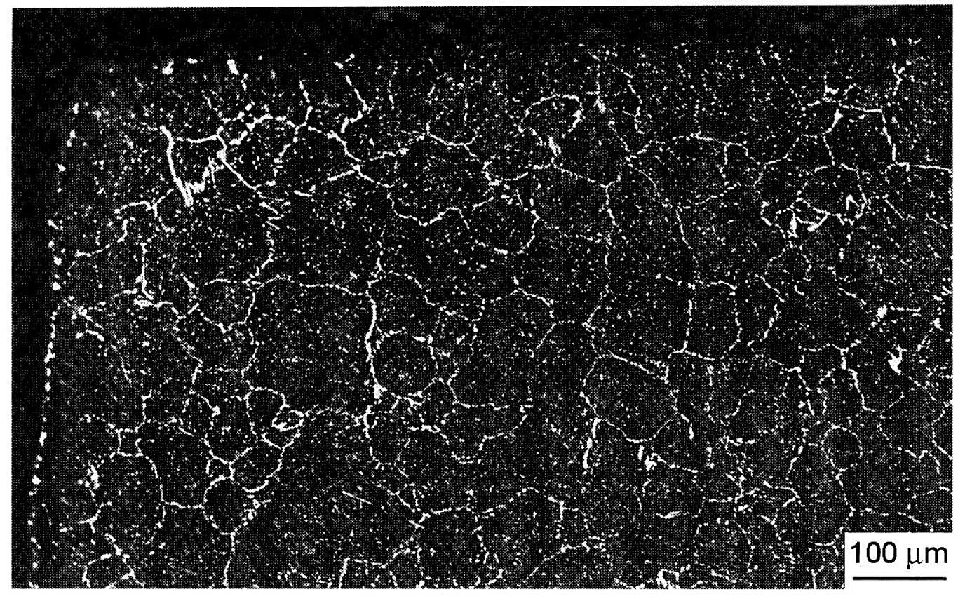
Austenitizing dissolves alloy carbides, and the higher the austenitizing temperature the more of them dissolve. On cooling the process runs in reverse. The carbon and alloy that went into solution have to leave it again, and they leave it at the sites where the energy is highest, which are the prior austenite grain boundaries. What forms there is a film of carbide between the grains. The film weakens the interface, and a weakened grain boundary is where a crack starts and how it travels.
On the continuous cooling transformation diagram the precipitation is marked by dashed lines, and the position of those lines is the practical warning. Raising the austenitizing temperature moves them to the left, which means the carbide film starts to form at cooling rates that would previously have been fast enough to avoid it. A quench that was adequate for one austenitizing condition is not adequate for a hotter one.
Two signatures identify this damage in a failed part. The first is a very strong etch at the prior austenite grain boundaries, because the interface between carbide and steel corrodes more readily than the matrix around it. The second appears in the more severe cases, where the fracture itself is intergranular and runs along the old grain boundaries instead of through the grains.
Under the microscope the carbide film appears as a continuous network on the prior austenite boundaries.
Bainite instead of martensite
Slow cooling has a second consequence, and it works in the same direction. If the cooling rate falls far enough, the transformation product is bainite instead of martensite, and bainite has lower toughness than martensite at the same hardness. The precipitation needed for secondary hardening is barely affected, so the tool can still temper to the specified hardness while carrying a structure that cracks easily. The hardness reading comes out on specification and the toughness does not.
Section size works against the quench
A larger section cools more slowly in the same medium, and the core of a large block cools more slowly than its surface. The source measured this on H13 with Charpy V-notch specimens cooled at rates that simulate the core of a 150 mm and a 300 mm round bar, together with a 25 mm specimen air cooled, each at several austenitizing temperatures. Toughness fell as the austenitizing temperature rose and as the simulated section grew, and both of those changes lower the cooling rate. The tests were run at room temperature and at 425 °C, and the order of the three conditions holds in both.
| Simulated condition | Cooling rate | Toughness against a small air cooled specimen | What it means for a real part |
|---|---|---|---|
| 25 mm, air cooled | The fastest of the three | The highest of the three | The condition a small tool can be quenched into. |
| Core of a 150 mm round | Slower | Lower, and lower again as the austenitizing temperature rises | A medium block is already at risk in the core. |
| Core of a 300 mm round | The slowest of the three | The lowest | Even a strong quench medium cannot protect the core of a large block. |
Charpy V-notch toughness of H13 cooled at rates that simulate the core of round bars, at room temperature and at 425 °C. The fall in toughness at the largest section is the reason heavy tools are sensitive to embrittlement in the core.
What a controlled heat treatment study measured on H13
The source ran the same grade through three hardening conditions, all aimed at 45 HRC, and measured impact toughness in each. The first is the recommended treatment, hardening at 1020 °C with a double temper at 610 °C. The second simulates a furnace that can only reach 900 °C, so the steel is austenitized at 890 °C and tempered at 250 °C to hold the hardness. The third simulates the austenitizing temperature of a high speed steel, 1150 °C, with tempering raised to 640 °C to bring the hardness back to 45 HRC.
| Condition | Hardening | Tempering | Toughness against the recommended treatment | What else changed |
|---|---|---|---|---|
| Recommended | 1020 °C | 610 °C, twice for 2 h | The reference condition | The structure the grade is specified for. |
| Low austenitizing | 890 °C | 250 °C | Down by about 40 percent | Incomplete austenite transformation leaves a heterogeneous structure, and the softening rate in service is about six times the expected one. |
| High austenitizing | 1150 °C | 640 °C | Down by about 90 percent | Coarse austenite grains, ASTM 3 to 4 against the 7 to 10 the grade should show, with proeutectoid carbide on the grain boundaries. |
Impact toughness measured on H13 tempered to 45 HRC under three hardening conditions. Both of the alternatives lose toughness without any gain in the hardness that was the target.
The high temperature condition deserves a careful reading, because it does one thing that is useful and one thing that is not. Dissolving more carbide puts more alloy into solution, which strengthens the secondary hardening, so the tempering temperature has to be raised about 30 °C to reach the same hardness. That is a real gain in tempering resistance. It is bought with a coarse grain size and a carbide film on the grain boundaries, and those cost far more toughness than the resistance is worth.
High speed steel has a narrower window
High speed steels are the extreme case, because their hardening temperatures sit close to the solidus. The margin is less than 50 °C. M2 is normally hardened at about 1200 °C. Above about 1220 °C the steel loses toughness without gaining hardness, and above about 1240 °C liquid forms in the carbide rich areas of the microstructure and the steel is spoiled. In a grade like this the austenitizing temperature is not a parameter to be traded, it is a limit to be respected.
Practice that avoids the embrittlement
Everything follows from preventing a slow quench. Hot work tool steels were traditionally oil quenched, and today vacuum heat treatment with pressurized nitrogen quenching is common. In the vacuum route the cooling rate is set by the nitrogen pressure and the gas circulation, and the control has to be right in both directions. A quench that is too strong, or uneven, distorts the tool or cracks it outright. A quench that is too slow embrittles the grain boundaries. The source points to the North American Die Casting Association guidance for H13, which covers the vacuum hardening practice and the use of coupons for destructive testing after the treatment.
The second lever is the order of the operations. The risk of embrittlement in the core rises with section size, so a heavy tool with deep engravings should be heat treated after rough machining and not before it, so that the embrittled core is not the material the working surfaces are cut from. Die casting dies are usually heat treated after machining, and even then the cooling rate in the surface region has to be controlled, because on a die the surface is the region that has to survive thermal fatigue.
| Practice | What it controls | What goes wrong without it |
|---|---|---|
| Quench rate control in a vacuum furnace | Gas pressure and gas circulation | Too strong and too uneven, distortion or cracking. Too slow, a carbide film on the grain boundaries and bainite in the core. |
| Heat treatment after rough machining | Where the embrittled core ends up | Heat treating the finished tool leaves the embrittled material in the working region. |
| Coupon testing after hardening | Whether the treatment actually produced the properties | Hardness alone passes a treatment that has no toughness left in it. |
The three practices the source gives for heavy tooling. Each one is aimed at the same risk, that the hardness is on specification while the toughness is gone.
Slow cooling and grain boundary carbide embrittlement, printable PDF
The carbide film that forms at the prior austenite grain boundaries on a slow quench, the effect of section size and austenitizing temperature, the toughness measured on H13 under three hardening conditions, and the practice that avoids it, in one reference sheet with our contact details.
Where this leaves a tool steel enquiry
The quench media and the cooling rates they produce are collected on the H13 quenching and cooling rates page, and the cracks that a fast quench opens are on the quench cracking page. The microstructure a tool steel should show after a correct quench is on the H13 microstructure page and the microconstituents after hardening page. Bainite and its hardness at each section size are on the austempering and bainite chart. The toughness the grades are expected to hold is on the impact toughness chart and the fracture toughness chart, and the austenitizing window for the hot work and high speed grades is on the austenitizing temperature page.
Before you use these values
This page is a reference summary of a published study and it is not an Aobo Steel specification. The toughness figures and the heat treatment responses are reproduced from the source, which tested one grade under a defined set of conditions. The film that forms on the grain boundaries in a particular tool also depends on the melting route, the analysis and the furnace it is treated in. Final specification is confirmed on the job.
Source, Failure Analysis of Heat Treated Steel Components (L. C. F. Canale, R. A. Mesquita and G. E. Totten), ASM International, 2008.