
Tool Steel Bar Delivery Condition, As-Rolled and Annealed
Two bars of the same tool steel grade can arrive with different structures and different hardnesses, and the difference is decided by how the bar cooled after the last rolling pass and by which anneal it was given afterwards. This page collects the as-rolled structures of L6, S4, S5 and L1, the grain boundary carbide network that a high carbon grade picks up on the rolling line, and the mill annealed against fully annealed structures of W4, W1 and H26, so the delivery condition on a certificate can be matched against the structure in the bar.
What the as-rolled structure depends on
The structure a tool steel bar carries when it leaves the rolling line is set by the hardenability of the grade and by the cooling rate the bar saw after the last pass. A shock resisting grade with a moderate alloy content can come out either way, and the two S4 plates below are the same grade cooled at two different rates. Poor thermal contact with the cooling bed leaves the slow one as ferrite and pearlite, and a faster cool takes it into the bainite and martensite range and leaves the bar harder and more crack sensitive than the certificate suggests.
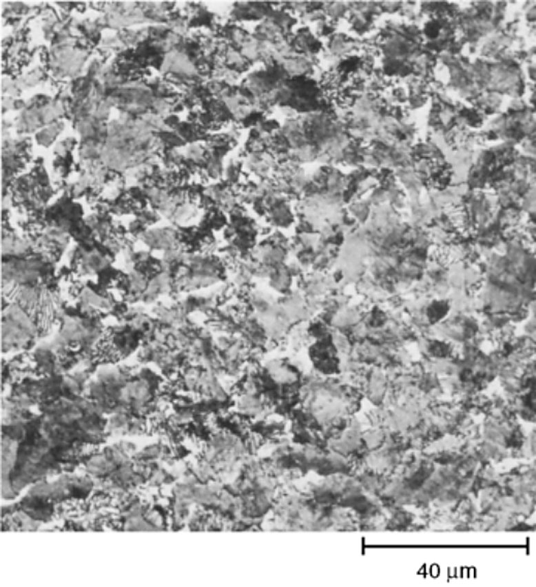
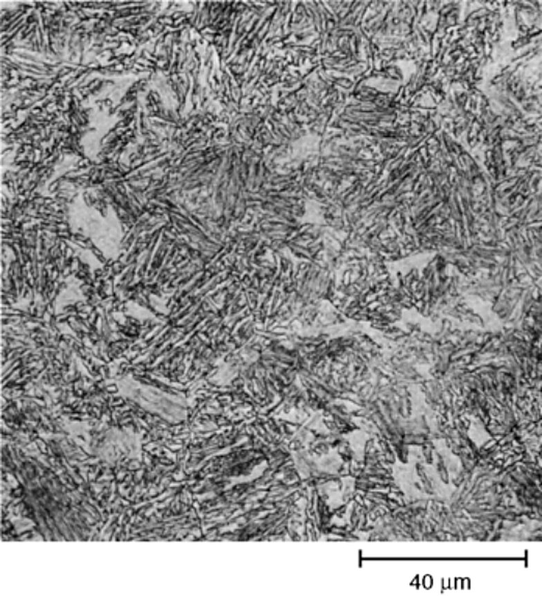
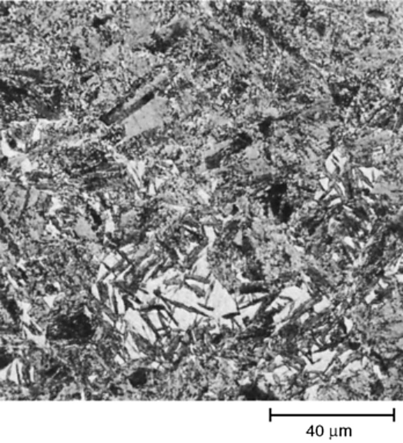
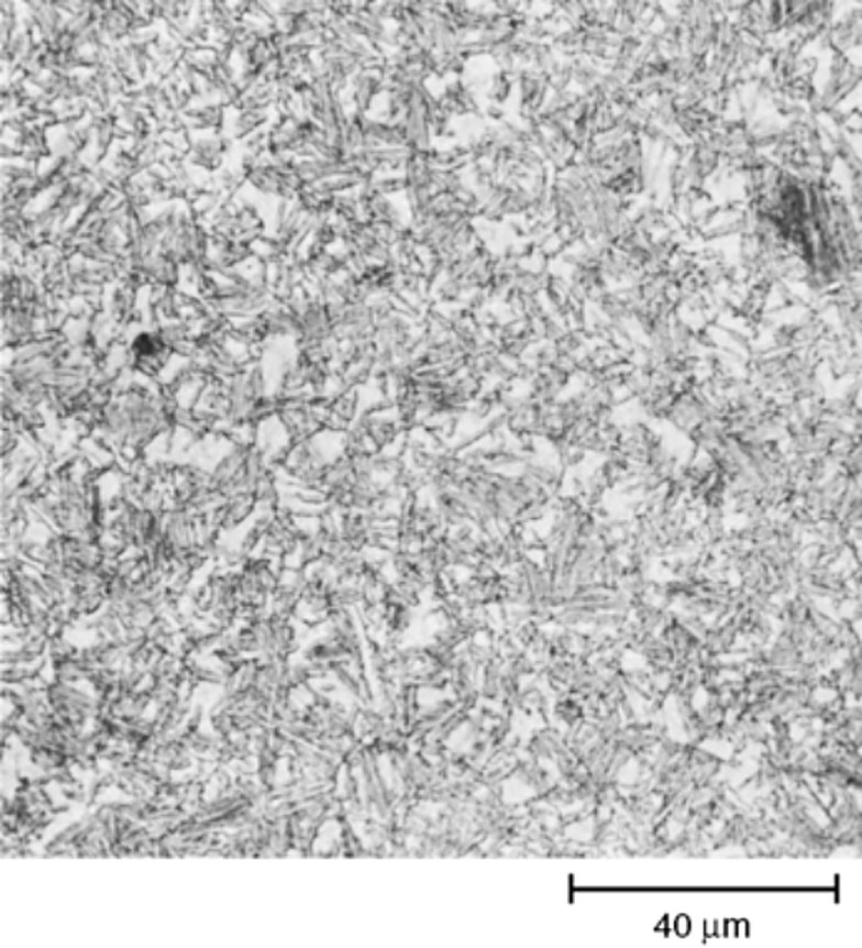
The same split appears across the family. L6 and S5 both arrive as bainite and martensite from a normal rolling cool, and the plates below are the reading to expect from an incoming inspection of those two grades.
Grain boundary carbide networks from the rolling line
A more serious structure than a hardness variation is the carbide network. Some tool steels, in particular the 5% chromium hot work grades and the 12% chromium plastic mould steels, form networks at the prior-austenite grain boundaries during hot working, and the high carbon water hardening grades form them when the bar cools through the carbide precipitation range after the last pass. L1 rolled and cooled leaves pearlite with a cementite network on the boundaries, which the alkaline sodium picrate etch colors so the network can be traced, and a 1.31% C water hardening grade shows the same network after cooling from the rolling temperature.
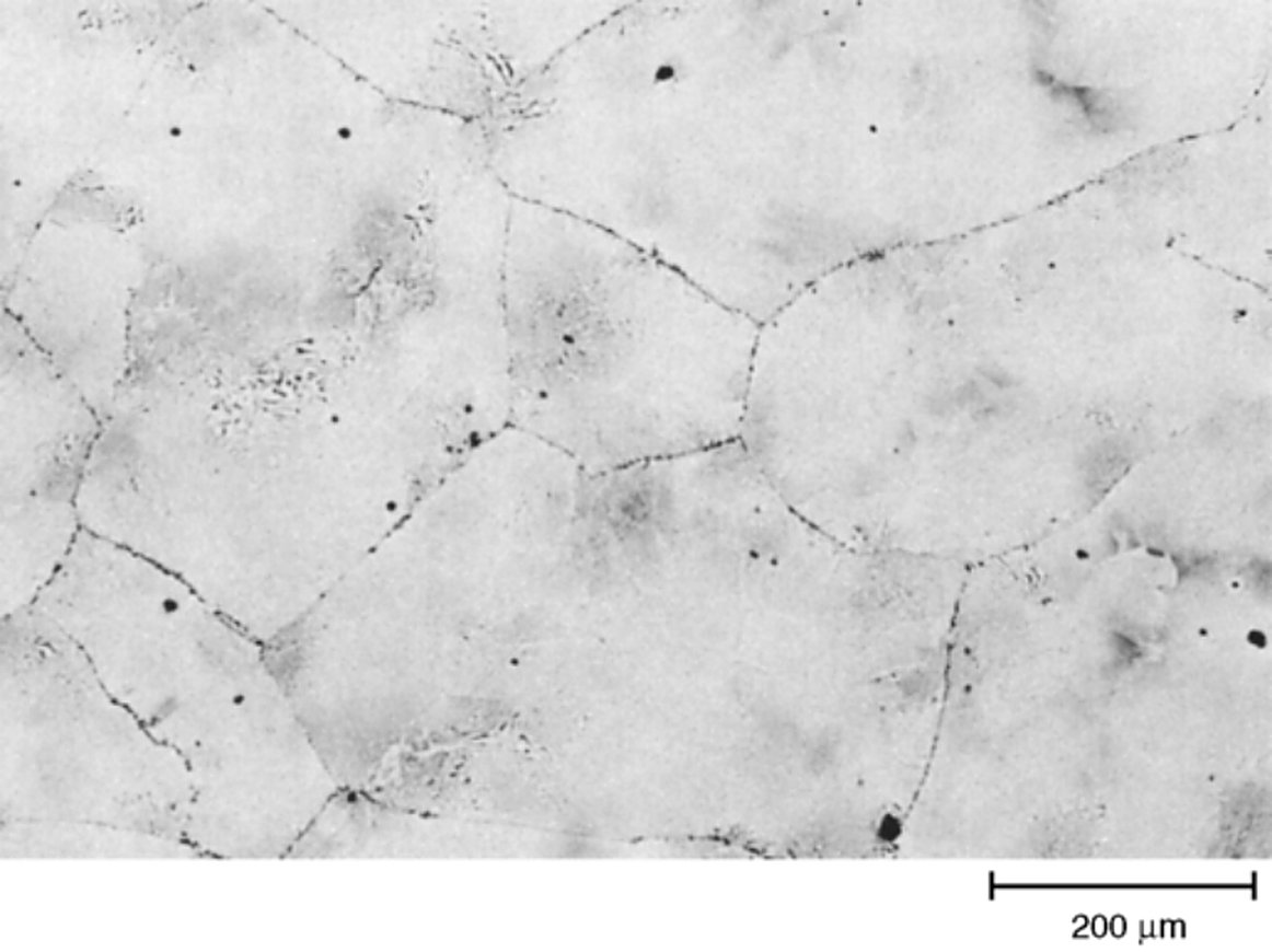
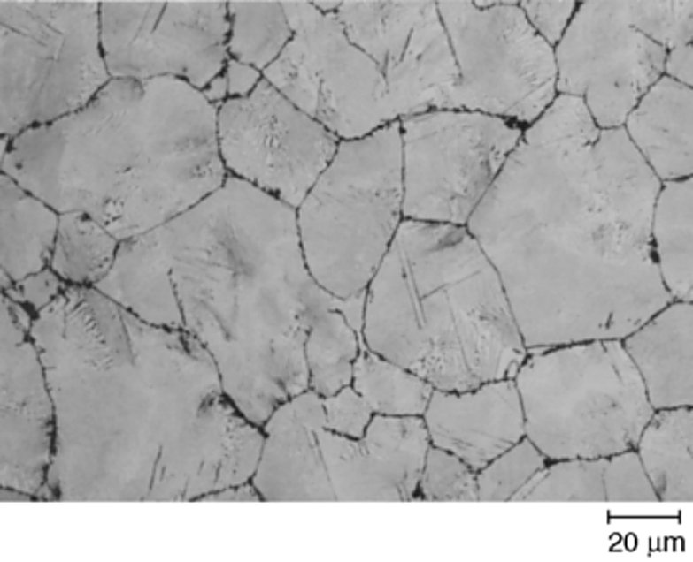
A network like that is difficult to remove during annealing and it damages tensile ductility and toughness even when it is only semicontinuous, which is why the grades that form one are normalized before they are annealed. Stringers of complex alloy carbide are the other harmful rolling line structure, and an example in H13 hot work steel is on the tool steel microstructure page. If a bar arrives with a heavy network and the parts made from it crack in service, the network is the first structure to look at, and it is checked on the annealed bar before the material is released to the shop.
Mill annealed against fully annealed
A delivery described as annealed can mean two different things, and the difference is worth a question at the order stage. A mill anneal is a subcritical anneal carried out at the mill to bring the bar into a machinable condition, and it does not dissolve the lamellar pearlite that the rolling line left behind. A full anneal austenitizes the steel and cools it through the transformation range slowly enough for the carbide to spheroidize completely. The three plates below are the same family in both conditions, and the hardness figures that go with them are 187 HB for the mill annealed W4 against 170 HB for the fully annealed W4 of the same chemistry.
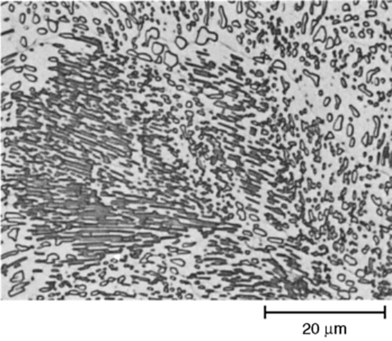
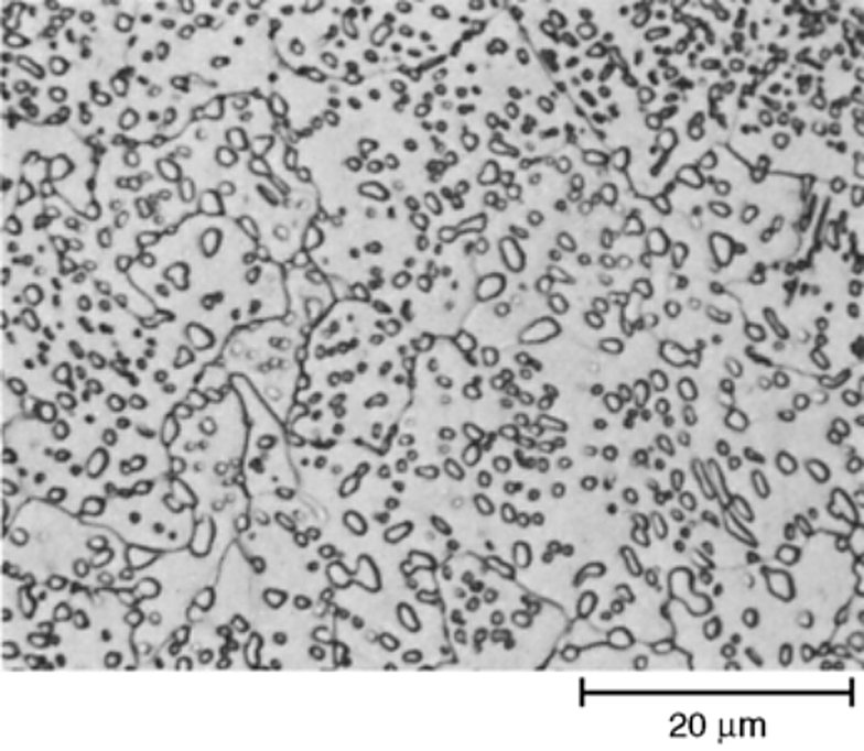
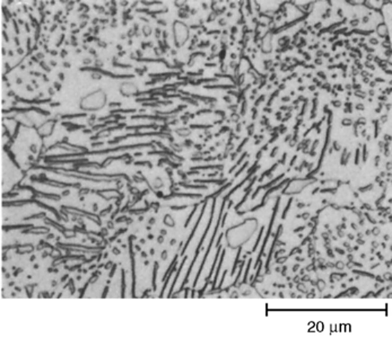
The practical consequence is that a mill annealed bar machines to a different finish, and it will respond to the hardening cycle a little differently because part of its carbide is still lamellar. For a die block that is going to be rough machined and then hardened, the difference rarely matters. For a part with a lot of machining or a tight dimension before hardening, it does, and the structure to ask for is a full anneal. The same distinction is behind the spheroidize anneal on the annealing and normalizing chart page.
Alloy carbide dispersion in a high alloy grade
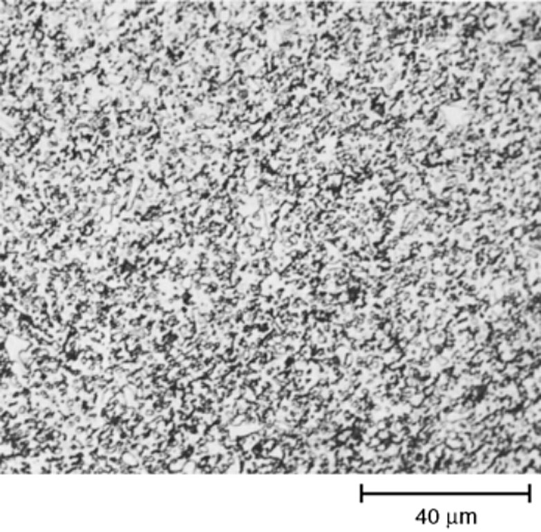
The high alloy water hardening and hot work grades do not hold lamellar pearlite at all in the annealed condition. H26 annealed from 900 °C with a controlled cool to 650 °C comes out at 22 to 23 HRC as a dispersion of fine alloy carbide particles in a ferrite matrix, which is the structure that makes the grade machinable at all. It is read with picral and HCl rather than nital, because the carbide sits finely enough that a plain nital etch does not separate it from the matrix.
Reading a delivery at the right magnification
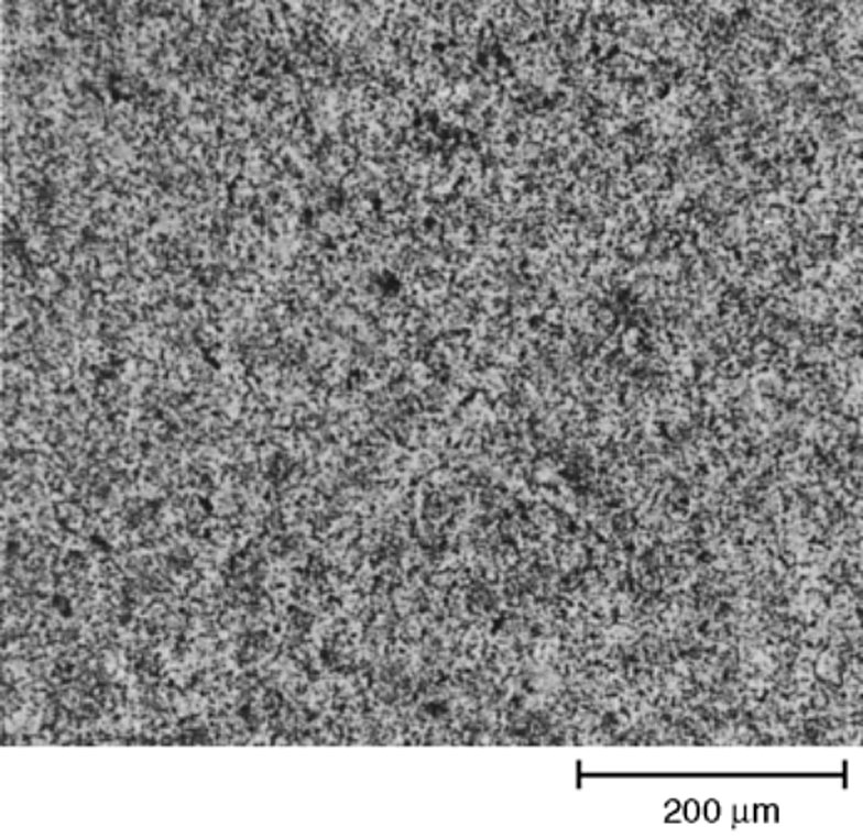
The last plate is the reason a delivery check is done at 500x or 1000x rather than at 100x. The same mill annealed A10 specimen that carries a resolvable structure at high magnification shows almost nothing but a grey field at 100x, and a check read at that magnification will pass a bar whose carbide is coarser than the specification allows. The routine check is a transverse section at 500x with the etchant the grade is normally read with, and the longitudinal section is added when the question is banding or a network rather than carbide size.
The etchants for each of these structures are listed on the tool steel microstructure page, and the furnace cycles that produce a fully spheroidized structure are on the annealing and normalizing temperature chart.
Compiled from ASM Handbook, Volume 9, Metallography and Microstructures, article Metallographic Techniques for Tool Steels by George F. Vander Voort, ASM International, 2004 (as-rolled and annealed microstructure sections, Fig. 11 to Fig. 14, Fig. 16, 19, 22 to 24, 34 and 36). Every caption was read from the searchable text layer of the file and checked against the printed plate, and each plate was cropped from the file at 1.5 times its printed pixel width. The plates are a reference summary of published practice rather than an Aobo Steel specification, so confirm the delivery condition, the annealing state and the hardness against the material test certificate before an order is placed.