
High Speed Tool Steel Heat Treatment
High speed steel is austenitized hotter than any other tool steel and tempered more than once, and the two habits belong together. The high austenitizing temperature is what dissolves the alloy carbides the grade depends on, and it is also what leaves 20 to 30% retained austenite behind after the quench. That austenite does not transform on the first cool, so it needs a second temper and sometimes a third. This page collects the practice data for that sequence from the source article, together with the liquid nitriding cycle for high speed steel cutting tools, the recommended hardness for chasers and taps, and the full heat treating route for M50 bearing steel. Where a figure could be redrawn from its own numbers it was, and the rest are reproduced from the source plate with the caption saying which is which.
Austenitizing temperature sets the as-quenched hardness
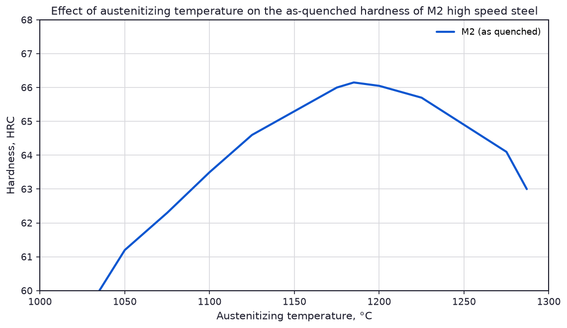
Hardness after the quench is a compromise between carbide dissolution and grain growth. At the bottom of the range the austenite never dissolves enough carbon and alloy to give the steel its full hardening response, so the as-quenched hardness falls away quickly. At the top of the range the carbides dissolve, the hardness peaks, and then grain growth and the rising retained austenite fraction start to pull it back down again. Fig. 1 shows the shape of that curve for M2, and the peak sits between 1170 and 1200 °C. A shop that has to choose one austenitizing temperature for a mixed load will usually pick a point just past the peak, because the hardness lost on the high side is smaller than the hardness lost on the low side.
Multiple tempering and retained austenite
A temper that is too cold or too short does not condition the retained austenite left after the quench. That austenite holds until the steel cools from the second temper, and then it transforms to fresh, untempered martensite, which is why a third temper is sometimes needed. The practical rules that follow are that the work must cool to room temperature between tempers and that the second temper adds almost no hardness while it does add toughness. Table 1 shows the effect on mechanical properties for T1, and the torsion-impact strength roughly doubles between the shortest single temper and a double temper of the same total time.
| Time at tempering temperature | Hardness, HRC | Bend strength, MPa (ksi) | Torsion-impact strength, J (ft · lbf) |
|---|---|---|---|
| Single tempering at 565 °C (1050 °F) | |||
| 6 min | 65.1 | 2150 (312) | 22 (16) |
| 1 h | 65.7 | 1860 (270) | 41 (30) |
| 2 1/2 h | 65.0 | 2810 (408) | 65 (48) |
| 5 h | 64.5 | 2590 (376) | 65 (48) |
| Double tempering at 565 °C (1050 °F) | |||
| 2 1/2 h + 2 1/2 h | 64.5 | 3130 (454) | 85 (63) |
Source, Table 11 of Heat Treating of Specific Classes of Tool Steels. The source notes that the second temper gives a negligible increase in hardness and that the steel should be cooled to room temperature between tempers.
Refrigeration treatment
A refrigeration treatment converts retained austenite to martensite and is recommended for the highly alloyed high speed steels such as M42, M3 class 2 and CPM Rex 60. It works best straight after the quench. The tool is cooled to at least -85 °C (-120 °F) and then tempered or retempered at the normal tempering temperature. A carburized surface responds to the same treatment even when it has already been tempered.
Nitriding high speed steel cutting tools
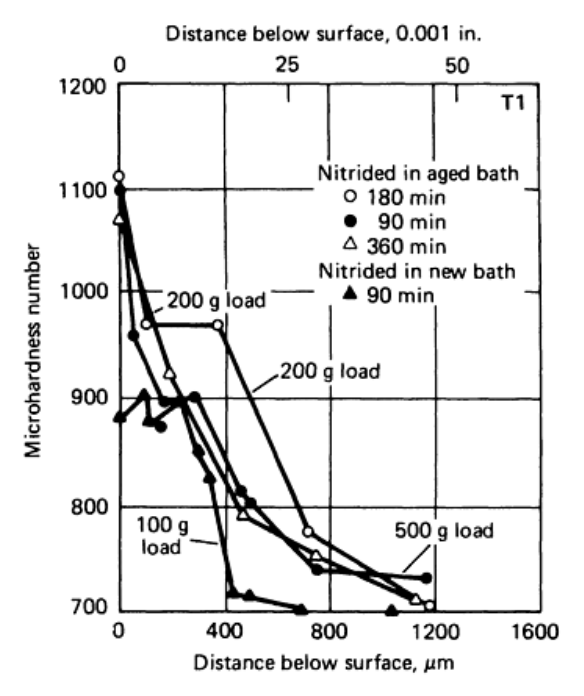
Liquid nitriding is preferred over gas nitriding for high speed steel cutting tools because it produces a more ductile case with a lower nitrogen content. The cycle is short and seldom exceeds one hour at 565 °C (1050 °F). Table 2 shows how the nitrogen content of the surface layer builds with time, and Table 3 shows the carbon that the cyanide bath also introduces. A tool nitrided in a fresh bath or for a short time carries a steep nitrogen and hardness gradient. The source recommends a longer immersion, a higher temperature or a thoroughly aged bath to flatten that gradient, because a steep gradient is what makes the case brittle. When the immersion time is short, the cyanate content of the bath should stay above 6%.
| Time at 565 °C (1050 °F) | Nitrogen, % |
|---|---|
| 3 min | 0.06 |
| 10 min | 0.093 |
| 30 min | 0.15 |
| 90 min | 0.26 |
| 3 h | 0.58 |
| 6 h | 1.09 |
Source, Table 12 of Heat Treating of Specific Classes of Tool Steels. Nitrogen content of the first 0.025 mm (0.001 in.) surface layer of a T1 high speed steel nitrided in a liquid bath at 565 °C.
| Nitriding temperature, °C | Nitriding temperature, °F | Time, min | Surface carbon, % |
|---|---|---|---|
| 455 | 850 | 30 | 0.85 |
| 510 | 950 | 30 | 0.99 |
| 565 | 1050 | 30 | 1.18 |
Source, Table 13 of Heat Treating of Specific Classes of Tool Steels. Carbon content of the first 0.025 mm (0.001 in.) surface layer of a steel that originally contained 0.705% C. The source states that part of the carbon sat in pits on the surface rather than being diffused into the steel, and that those pits are shallower than ordinary grinding marks.
Steam treating
Steam treating develops a blue-black oxide film that reduces the adhesion between the tool and the workpiece. The work is heated to about 370 °C (700 °F) and equalised, steam is admitted at a controlled rate for roughly the first part of the cycle, the furnace is then partly sealed to build a positive steam pressure and the temperature is raised to 525 °C (975 °F). The film is relatively insensitive to temperature up to about 580 °C (1075 °F), so the treatment can be combined with a normal temper. It also cleans up the pitting that adhering salt leaves on tools hardened in a salt bath.
Hardness for chasers and taps
Hardness for a threading tool follows the pitch and the material being cut. Coarse pitch threads take a harder chaser than fine pitch threads, and Acme threads take a softer one because the wide chip load punishes a brittle edge. Chasers for cast iron and plastics are taken to the maximum hardness the grade will reach, since those materials are cut with little cutting force and the tool life comes down to abrasion resistance.
| Threading tool | Hardness, HRC | |||
|---|---|---|---|---|
| Fine-pitch threads | Coarse-pitch threads | Acme threads | Pipe threads | |
| Chasers | 61-63 | 64-65 | 60-62 | . . . |
| Taps | 63-65 | 63-65 | 62-64 | 62-64 |
Source, Table 14 of Heat Treating of Specific Classes of Tool Steels. The source adds that chasers for cast iron or plastics are hardened to the maximum attainable hardness of the grade, while Acme thread chasers are sometimes deliberately underhardened.
M50 bearing steel
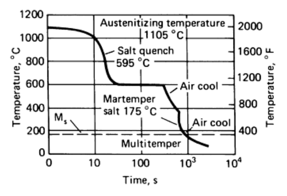
M50 has a nominal composition of 0.83C-4.0Cr-4.0Mo-1.0V and a martensite start temperature of about 163 to 166 °C (325 to 330 °F). Any cooling rate that brings the austenitized part to 205 °C (400 °F) or below within 15 minutes will harden it, so the cooling route is chosen for distortion and residual stress rather than for hardness. The route the source recommends runs through a 540 to 595 °C (1000 to 1100 °F) salt quench, a 175 to 190 °C (350 to 375 °F) martemper bath and a series of tempers of 540 to 550 °C (1000 to 1025 °F), with a cool to room temperature between each one and a deep freeze either before the first temper or between the first and the second. Parts are austenitized at 1105 to 1120 °C (2025 to 2050 °F) for 3 to 10 minutes, and the interval between austenitizing and the martemper bath should not exceed 15 minutes.
| Cycles | Temperature, °C | Temperature, °F | Time (a), min |
|---|---|---|---|
| Two preheat baths | |||
| 1 | 675-730 | 1250-1350 | 10-15 |
| 2 | 815-870 | 1500-1600 | 5-15 |
| Three preheat baths | |||
| 1 | 675-730 | 1250-1350 | 10-15 |
| 2 | 815-870 | 1500-1600 | 5-15 |
| 3 | 955-1010 | 1750-1850 | 5-10 |
Source, Table 15 of Heat Treating of Specific Classes of Tool Steels. (a) The source states that the cycle time depends on the relative load size and the bath capacity.
What these numbers assume
Every figure on this page is the practice of the plant or the laboratory that produced the source table, and it is a reference point rather than a released cycle. Furnace type, load weight, section size and the actual composition of the heat all move the result, and a high speed steel is unforgiving of a soak that runs long at the top of the austenitizing range because the grain grows and the toughness does not come back. Check the hardness and the grain size on a first article before the cycle is written into a route card.
Source: ASM Handbook, Volume 4, Heat Treating, ASM International, 1991.