
Tool Steel Austenitizing Temperature and Microstructure
The austenitizing temperature of a tool steel is not a range that came out of a handbook by accident. It was fixed by running a series of specimens through increasing temperatures and reading two things on each one, the as-quenched hardness and the prior-austenite grain size. This page collects that series for S7 and O1, the case and core of a brine quenched W1 bar, and the carbide quantity left in high speed steel after austenitizing, so the effect of running a furnace too cold or too hot is visible rather than described.
How the correct austenitizing temperature is established
The temperature is set experimentally by an austenitizing series. Samples are heated to a range of temperatures and quenched at a rate that suits the hardenability of the grade. Each as-quenched sample is fractured and the prior-austenite grain size is rated on the fracture by the Shepherd comparison method. The same samples are then ground on one of the fracture faces and hardness tested.
Two curves come out of that work and they move in opposite directions. Hardness rises as more carbide goes into solution, levels off, and then falls away again. Grain size stays roughly constant up to the temperature where hardness levels off, and then it coarsens. The correct austenitizing temperature is the point where hardness is at its highest and the grain is at its finest, and a dilatometer run usually precedes the series to bracket that window.
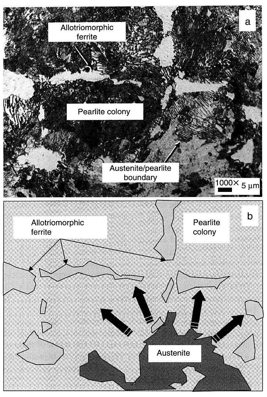
What the austenitizing hold is actually doing is shown below. A ferrite and pearlite structure is taken into the intercritical range for a short time, and austenite appears first in the pearlite colonies, because that is where the carbon sits. It then grows along the colonies and back into the ferrite until the equilibrium austenite fraction for that temperature is reached, and a hold that is cut short leaves part of the structure unconverted.
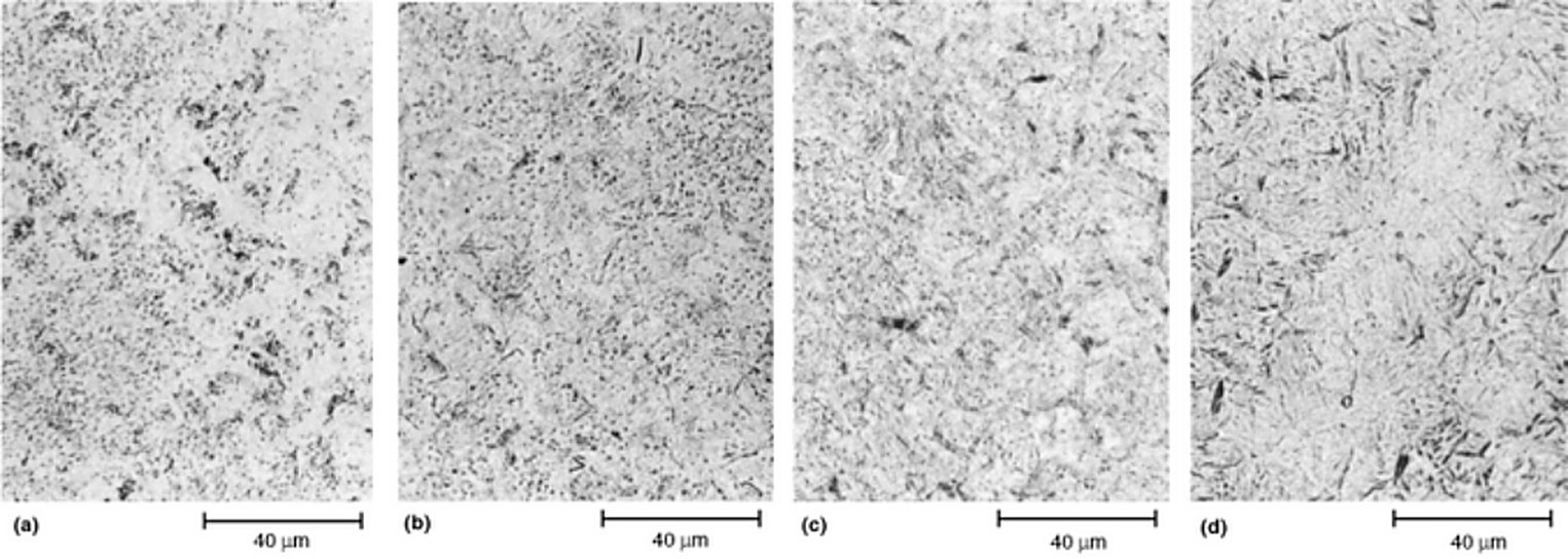
Underaustenitizing and overaustenitizing in S7
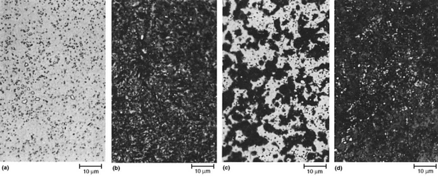
S7 is a shock resisting grade with about 0.5% carbon and a preferred austenitizing temperature of 940 °C, and it is sensitive in both directions. Run it cold and not enough carbide is dissolved to reach full hardness. Run it hot and all of the carbide goes into solution, which removes the pinning that would normally hold the grain boundary in place. S7 is not aluminum killed, so there is no aluminium nitride to stop the grain from growing, and the structure coarsens quickly. The four plates below are the same grade at 915, 925, 940 and 955 °C.
Steel at the upper end of the carbon range behaves differently again. A 1.3% C carbon tool steel is hypereutectoid and holds only cementite, which dissolves easily, so the iron-carbon diagram is enough to set the temperature. Maximum hardness comes from putting about 0.60 to 0.65% C into solution, and the rest of the cementite is meant to stay undissolved as residual carbide. A structure with no residual carbide at all has been run too hot.
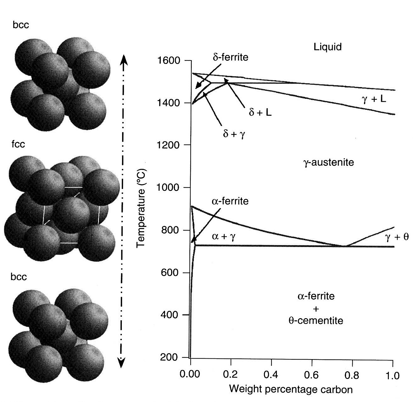
Every temperature above is read off the metastable iron-carbon diagram, which is the diagram below. Its field boundaries, and not any alloy data, set the austenitizing temperature for the plain carbon grades; the alloyed grades sit away from it, which is why they are set from their own series instead.
The austenitizing series for O1, with grain size
O1 is an oil hardening grade with about 0.9% carbon and a preferred austenitizing temperature of 800 °C. The series below runs from the correct temperature to a severely overheated one, and the numbers printed with each plate are the hardness and the ASTM grain size that came off the same specimen. The grain goes from 9.5 to 9 to 7 and then to 3, while hardness barely moves, which is the point of using grain size as the control and not hardness alone.
The other change visible in the series is retained austenite. Carbon dissolved in the austenite depresses the martensite start temperature, so the higher the austenitizing temperature, the more austenite is still untransformed when the steel reaches room temperature. In O1 the retained austenite only becomes visible in the light microscope at the top of the range, in the 1100 °C specimen. The same rule applies to D2, where retained austenite is present at the correct austenitizing temperature and still cannot be seen until a substantial amount is there, generally more than 10%. The five temperature D2 series is on the tool steel microstructure page.
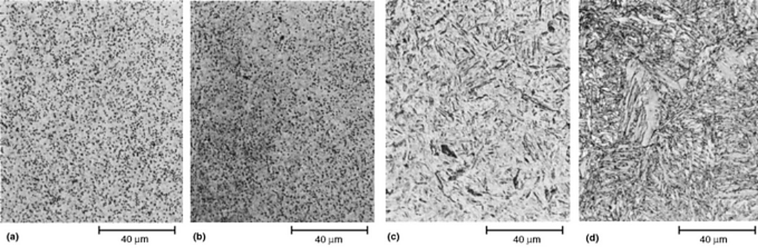
Case, transition zone and core in a quenched bar
A carbon tool steel is usually not through hardened, so the same bar carries three different structures at once and the micrograph has to be read with that in mind. The plates below are a 19 mm W1 bar after a brine quench, from the case through the transition zone into the core. The case is high-carbon martensite with undissolved carbide at 64 HRC, the transition zone is at 55 HRC with martensite, outlined carbide and dark pearlite, and the core at 42 to 44 HRC is a fine pearlite matrix with patches of martensite. Residual cementite is present at all three positions, which is correct for the grade, and the hardness the part is sold at has to be quoted with the position it was measured at.
How much carbide is left after austenitizing
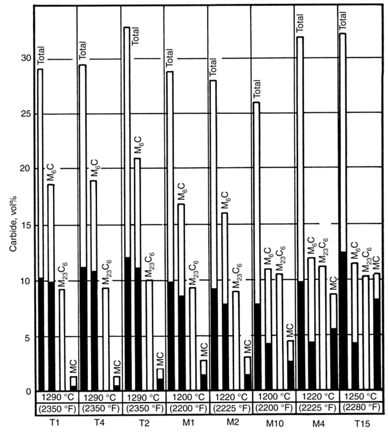
In high speed steels the austenitizing temperature decides how much of the carbide population survives into the hardened tool, and that in turn decides where the balance between wear resistance and toughness falls. The chart below compares the carbide quantity in the annealed condition with the quantity after austenitizing at the hardening temperature printed for each steel. The dissolved fraction is what raises hardness in the quench and feeds the secondary hardening on tempering, and the undissolved fraction is what carries the wear resistance.
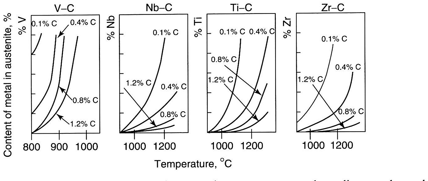
How much of that carbide can be taken back into solution is a question of solubility. The panels below give the amount of each carbide-forming element that austenite can hold at a given temperature, for four carbon levels.
What to check on an incoming heat
Two numbers should come with the steel, and the plates above are what they mean. The austenitizing temperature the mill recommends has to be the one whose specimen shows the finest grain at full hardness, and the hardness the tool is sold at is the hardness of the position it was tested in. A supplier who quotes a hardness without saying whether it is a surface or a core reading has left the austenitizing question open. The hardness a grade keeps once it is running hot is on the hot hardness chart, and the temperature range for each grade is set out on the D2 austenitizing temperature page for that grade.
Compiled from ASM Handbook, Volume 9, Metallography and Microstructures, article Metallographic Techniques for Tool Steels by George F. Vander Voort, ASM International, 2004 (heat treated microstructures section, Fig. 39 and Fig. 45 to Fig. 48). Every caption was read from the searchable text layer of the file and checked against the printed plate, and each plate was cropped from the file at 1.5 times its printed pixel width. The plates are a reference summary of published practice rather than an Aobo Steel specification, so confirm the austenitizing temperature and the hardness position against the material test certificate before a process sheet is written.