
Quench Cracking in Tool Steel: Mechanisms, Identification, and Prevention
What is Quench Cracking?
Quench cracking is a failure that occurs during or shortly after quenching. Cracks typically initiate at the surface and propagate inward along longitudinal or radial paths. Once formed, the component cannot be recovered.
Why Quench Cracking Occurs
Quench cracking occurs when internal stresses generated during cooling and transformation exceed the hardened structure’s tensile strength. The resulting fracture is read the same way as any other, and the marks that date a crack to the quench are shown in the fracture surface features chart.
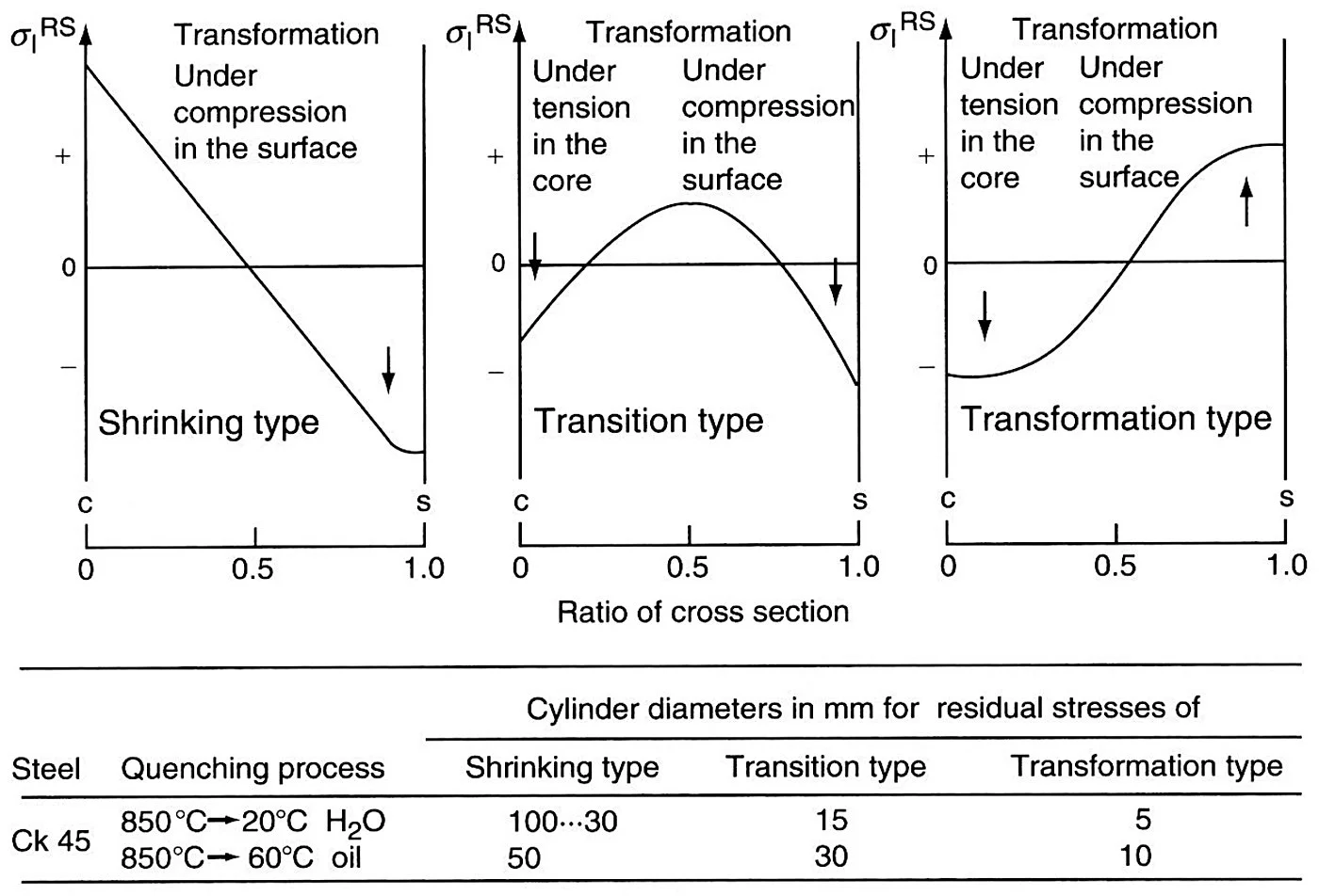
During quenching, the surface cools and contracts first while the core remains hot, creating a temperature gradient that introduces mechanical stress across the section. At the same time, the austenite-to-martensite transformation produces volumetric expansion. Because the surface transforms first, it expands while the core remains ductile and can accommodate deformation.
As cooling continues, the core reaches the transformation temperature and begins to expand. At this stage, the surface has already transformed into rigid martensite and can no longer deform plastically. The expanding core forces tensile stress onto the surface. When this stress exceeds the material’s local strength, cracks initiate at the surface and propagate inward.
How the crack then runs depends on quench severity, and the pattern changes systematically with it.
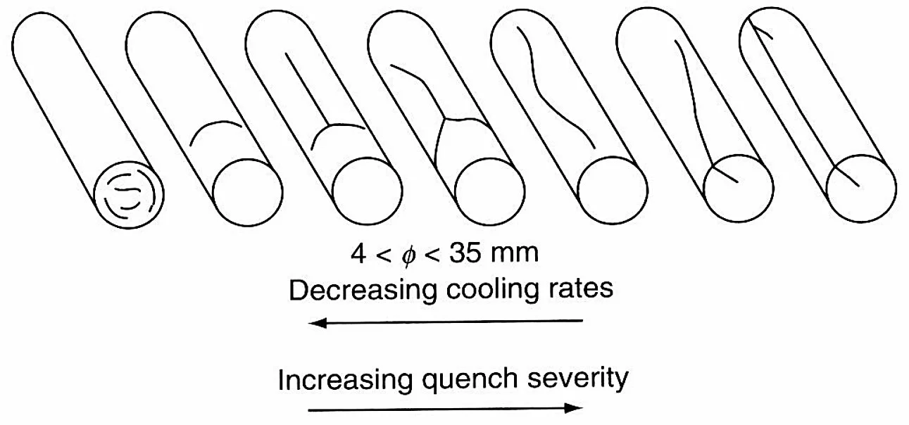
→ Learn how quenching works in tool steel heat treatment
Which effect wins depends on the section and grade, and there are three standard outcomes. The panels below are the three residual stress patterns a hardened cylinder can end up with.
Factors Influencing Cracking Risk
Cracking risk depends on how stress is generated and concentrated during quenching.
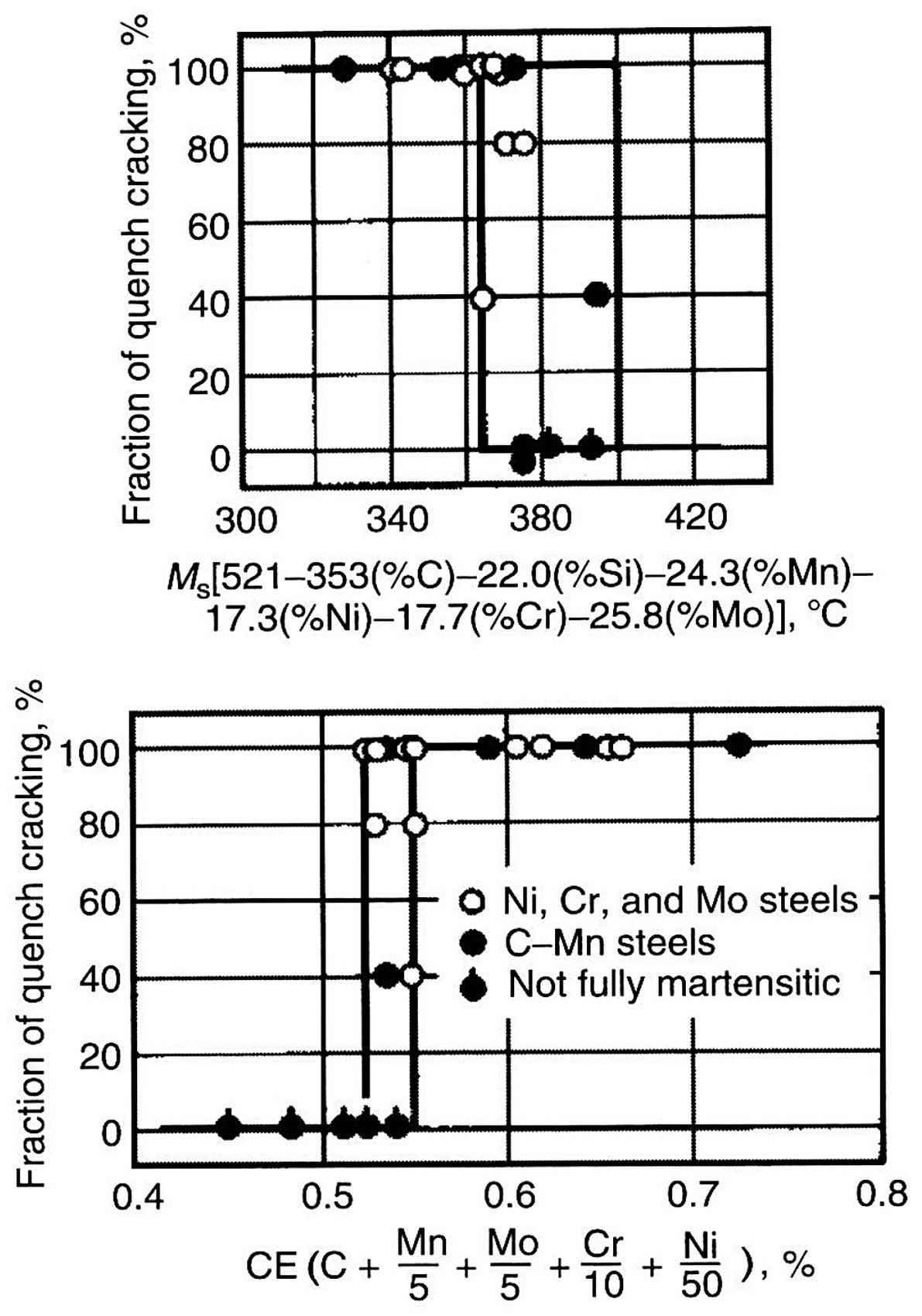
Material composition directly affects transformation behavior. Higher carbon content increases volumetric expansion and lowers transformation temperatures, reducing stress relaxation and increasing susceptibility to cracking.
Geometry controls heat extraction and stress distribution. Sharp corners, keyways, and large differences in section thickness create non-uniform cooling, which concentrates stress at specific locations.
Surface condition defines where cracks initiate. That surface is one link in a longer chain of causes, and the full chain, from design through service, is covered on the tool and die failure analysis page. Machining marks, stamping defects, and metallurgical discontinuities act as stress raisers. Surface decarburization further alters the transformation timing between the surface and the core, increasing the mismatch during cooling.
Austenitizing practice affects structural strength. Excessive temperature coarsens grains, reducing resistance to intergranular fracture during quenching.
The two material numbers that move the risk most are the martensite start temperature and the carbon equivalent, and the relation is not linear.
Identification in Practice
Quench cracks are identified by their origin, morphology, and metallurgical features.
Cracks typically initiate at the surface and follow prior austenite grain boundaries, resulting in an intergranular fracture path. If tempering occurs after cracking, oxidation inside the crack produces temper colors or scale, indicating that the crack formed before tempering. In contrast, cracks formed after heat treatment do not show internal oxidation.
The surrounding microstructure does not show decarburization because cracking occurs after the high-temperature stage.
Prevention and Mitigation
Prevention focuses on reducing stress concentration and synchronizing transformation throughout the section.
Design geometry to avoid sharp transitions and large thickness differences to promote uniform cooling. Surface preparation must eliminate machining defects and prevent decarburization during heating.
Select quenching methods to control the cooling rate and reduce temperature gradients. Processes such as martempering equalize temperature before transformation, significantly reducing internal stress.
Perform tempering immediately after quenching, while the component is still warm, to relieve residual stresses and prevent delayed cracking.
Material Selection and Hardenability
Material selection controls the stress level developed during quenching.
Low-hardenability steels require rapid cooling to achieve full hardness, which produces steep thermal gradients and high internal stress. These steels are suitable only for simple geometries.
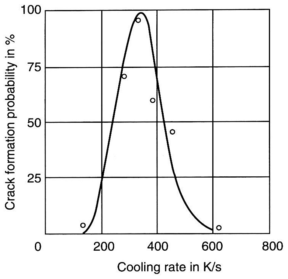
The cooling rate itself has a dangerous band, and it is measurable.
High-hardenability tool steels transform at slower cooling rates, allowing air or mild quenching. This reduces temperature gradients and internal stress, making them better suited to complex shapes and large sections. The section each grade will harden through at a given quench is shown in the tool steel hardenability chart.