
Tool Steel Distortion and P/M Tool Steels
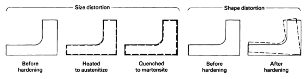
Distortion is the part of a tool steel heat treatment that the hardness tables never show, and it comes in two forms that are usually confused with each other. Size distortion is the change in the actual dimensions of the part, and it is a property of the steel and the cycle. Shape distortion is the loss of form, the bow and the out-of-round, and it comes from the way the part was heated and cooled. This page carries the source data on what the microstructure after hardening contains, how much a high speed steel bar moves, what powder metallurgy buys in out-of-roundness, and the aging treatments for the maraging grades.
Size distortion and shape distortion are different problems
The distinction matters because the two have different causes and different fixes. Size distortion tracks the volume change of the steel itself, so it happens even to a part with no stress in it and no variation from end to end. Shape distortion is where the part stops matching itself, and it comes from uneven heating, uneven cooling, residual stress from machining and a section that changes thickness faster than the steel can move. A shop that measures only the overall length of a block will see the size distortion and miss the shape distortion completely, which is why a distortion check belongs on the dimensions that matter to the finished tool.
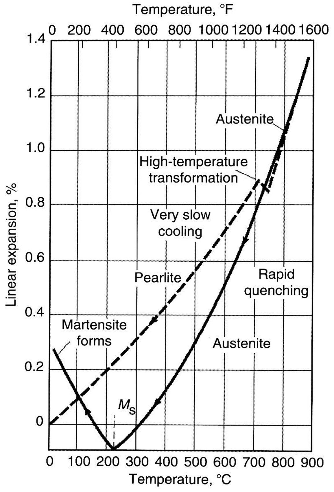
Both kinds of distortion start in the length change the steel goes through on the way down, and that length change depends on the route.
What the structure contains after the quench
The size change a tool steel shows on hardening is set by how the structure that comes out of the quench differs from the annealed structure that went in. That structure is a mixture of three things, and the table below measures all three on four grades quenched from their recommended austenitizing temperatures. The interesting column is not the hardness. It is the split between martensite, retained austenite and undissolved carbide, because that split tells the whole story of what the temper can and cannot do afterwards. The low-alloy grades come out almost entirely martensitic with little austenite left, and a high-carbon high-chromium grade like D2 comes out with 40% retained austenite and 15% undissolved carbide, which is a completely different starting point for the temper.
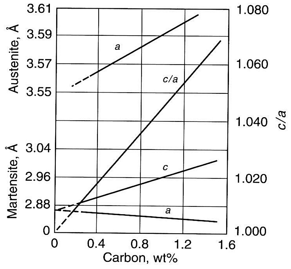
Underneath the length change is a lattice change, and the lattice is what the carbon content acts on.
| Steel | Hardening treatment | As-quenched hardness, HRC | Martensite, vol% | Retained austenite, vol% | Undissolved carbides, vol% |
|---|---|---|---|---|---|
| W1 | 790 °C (1450 °F), 30 min, WQ | 67.0 | 88.5 | 9 | 2.5 |
| L3 | 845 °C (1550 °F), 30 min, OQ | 66.5 | 90 | 7 | 3.0 |
| M2 | 1225 °C (2235 °F), 6 min, OQ | 64 | 71.5 | 20 | 8.5 |
| D2 | 1040 °C (1900 °F), 30 min, AC | 62 | 45 | 40 | 15 |
Source, Table 1 of Control of Distortion in Tool Steels. WQ, water quench; OQ, oil quench; AC, air cool. The four steels were quenched from their recommended austenitizing temperatures and the microconstituents were measured on the as-quenched structure.
How much a high speed steel bar moves
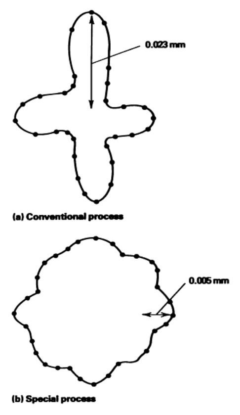
A bar does not distort evenly around its circumference, and the difference between the largest and the smallest diameter after hardening is a direct measure of how uniform the treatment was. Fig. 2 shows the same section of bar after two different routes. The conventional route leaves a profile whose variations are visible to the eye, and the source quotes 0.023 mm between the high and low points. The special process leaves a far rounder profile at 0.005 mm, and the practical consequence is that less material has to be left on the bar for the finish grind.
What powder metallurgy changes
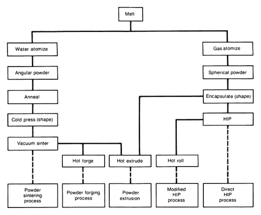
A powder metallurgy tool steel is made by atomizing the melt into powder and then consolidating it, so the ingot stage and its segregation never happen. The process route in Fig. 3 runs from the melt through either water or gas atomization, and the two branches lead to different powder shapes and therefore to different consolidation methods. The result carries two advantages that matter to a toolmaker. There is no macrosegregation and no porosity, and the carbides are fine and evenly spread rather than stringing out in bands. Both of those give a deeper hardening response and a faster response to the austenitizing treatment, which matters most for the molybdenum high speed steels because they decarburize quickly at temperature.
Out-of-roundness is the third advantage, and it is the one that shows up as money on the bar. The table below compares a P/M bar with a conventional bar of the same grade at three diameters, and the P/M bar is between two and four times rounder at every size. The gap widens as the bar gets larger, which is where conventional casting has the most trouble with segregation.
| Bar diameter, mm | Bar diameter, in. | Production method | Typical out-of-roundness (a), mm | Typical out-of-roundness (a), in. |
|---|---|---|---|---|
| 75 | 3 | P/M | 0.008 | 0.0003 |
| 75 | 3 | Conventional | 0.020 | 0.0008 |
| 125 | 5 | P/M | 0.013 | 0.0005 |
| 125 | 5 | Conventional | 0.033 | 0.0013 |
| 190 | 7.5 | P/M | 0.015 | 0.0006 |
| 190 | 7.5 | Conventional | 0.051 | 0.0020 |
Source, Table 4 of Control of Distortion in Tool Steels. (a) Maximum diameter minus minimum diameter after the normal hardening treatment. The comparison is between a powder metallurgy bar and a conventional cast and wrought bar of the same grade and diameter.
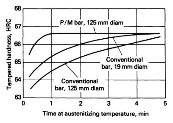
Fig. 4 shows what the finer and more uniform carbide distribution does to the hardening response. The two curves are the same grade, M25, one made by powder metallurgy and one cast and wrought, oil quenched from 1200 °C (2200 °F) and tempered three times at 550 °C (1025 °F). The P/M bar reaches its hardness in a shorter austenitizing time and holds a higher hardness at the long end, and the conventional bar of the same 125 mm diameter never catches it.
Maraging steels
Maraging steels sit at the edge of the tool steel family and they are the exception to almost everything above, because they do not harden by quenching at all. The steel is annealed soft, machined to shape, and then aged at a single temperature, which is why a maraging die can be finished before it is hardened and does not move in the process. The grade name carries its own specification, with a three digit number for the approximate tensile strength in ksi and a letter for the principal strengthener, so 18Ni C (250) is an 18% nickel steel alloyed with cobalt at about 250 ksi. The source does not recommend overaging or underaging, because both cost properties, so the aging temperature in the table is the treatment rather than a starting point for adjustment.
| Grade | Aging treatment (a), °C | Aging treatment (a), °F | Nominal hardness, HRC |
|---|---|---|---|
| 18Ni C (200) | 480 | (900) (b) | 44 |
| 18Ni T (200) | 480 | (900) (b) | 44 |
| 18Ni C (250) | 480 | (900) (b) | 50 |
| 18Ni T (250) | 480 | (900) (b) | 50 |
| 18Ni C (300) | 480 | (900) (b) | 53 |
| 18Ni T (300) | 480 | (900) (b) | 53 |
Source, Table 5 of Control of Distortion in Tool Steels. (a) The aging time is 3 to 6 h plus 1 h for each additional 25 mm (1 in.) of cross section. (b) An aging treatment of 530 °C (990 °F) is recommended for aluminium die casting dies, which gives hardness values a little lower, about 2 HRC below the figures shown.
What to check before release
Two numbers are worth having on the route card for any tool whose final dimensions matter. The first is the total size change expected from the quench and the temper, which the steel supplier can give for the grade and which is why the grade is chosen before the machining allowance is set. The second is a first article measurement on the dimensions that control the finished tool, taken after hardening and before the finish grind, because shape distortion cannot be calculated from a table at all. A part that comes out round but larger than expected is a size problem and can often be fixed by changing the allowance. A part that comes out oval is a shape problem, and the fix is in the furnace and the quench, not in the allowance.
Source: ASM Handbook, Volume 4, Heat Treating, ASM International, 1991.