
Tool Steel Heat Treating Practices
A tool steel performs the way its heat treating cycle prepared it, and most of the tool life that is lost in a shop is lost in the hours between the quench and the final temper. The tables on this page are the published practice data for that part of the route. They cover the safe delay between quenching and tempering, isothermal cycle annealing schedules, the time a load needs to reach the tempering temperature, the cycle times of an automated salt bath line for high speed steel, the endothermic atmosphere dew point that protects the surface during hardening, and the packing compounds used when a tool is annealed in a pack. Every figure is reproduced from the source tables and the source article, table number is given under each one so the original can be checked.
Time between quenching and tempering
Shock resisting tool steels are the grades most exposed to cracking in the interval after the quench. The steel has just transformed to martensite and the section carries the full transformation stress, and a water or a brine quench adds thermal stress on top of it. Tempering is what relieves that stress, so the delay before the tempering furnace is a process limit that belongs on the route card. The figures in Table 1 were measured in one plant on the S grades, and they show how quickly the allowance falls as the austenitizing temperature and the severity of the quench go up. The same plant found that a double temper is worth the extra cycle on the S steels, with the first temper run 30 to 55 °C (50 to 100 °F) below the second.
| Steel | Austenitizing temperature, °C | Austenitizing temperature, °F | Quenching medium | Allowable time prior to tempering, min |
|---|---|---|---|---|
| S1 | 900 | 1650 | Oil | 30 |
| S1 | 980 | 1800 | Oil | 15 |
| S2 | 845 | 1550 | Brine | 10 |
| S2 | 900 | 1650 | Brine | 5 |
| S3 | 815 | 1500 | Brine | 10 |
| S3 | 870 | 1600 | Brine | 5 |
| S4 | 870 | 1600 | Brine | 10 |
| S4 | 925 | 1700 | Brine | 5 |
| S4 | 900 | 1650 | Oil | 30 |
| S4 | 955 | 1750 | Oil | 15 |
| S5 | 870 | 1600 | Oil | 30 |
| S5 | 925 | 1700 | Oil | 15 |
Source, Table 3 of Heat Treating of Specific Classes of Tool Steels. Values determined by an extensive study conducted in one plant. The source notes that the allowable time may vary significantly with the size and shape of the part.
Cycle annealing schedules
Cycle annealing replaces a long slow furnace cool with two isothermal holds in the transformation range. It gives little advantage on a large load, because the centre of the load still has to come down slowly, but for a single tool that can be handled in a liquid bath or a small furnace it saves a substantial amount of furnace time. Table 2 gives the cycles for four grades, two cold work steels and two air hardening grades.
| Steel | Treatment |
|---|---|
| O1 | Heat to 730 °C (1350 °F) and hold for 4 h, heat to 780 °C (1440 °F) and hold for 2 h, cool to 690 °C (1275 °F) and hold for 6 h, then air cool |
| A2 | Heat to 900 °C (1650 °F) and hold for 2 h, cool to 760 °C (1400 °F) and hold for 6 h, then air cool |
| A6 | Heat to 815 °C (1500 °F) and hold for 2 h, cool to 650 °C (1200 °F) and hold for 6 h, then air cool |
| D2 | Heat to 900 °C (1650 °F) and hold for 2 h, cool to 775 °C (1425 °F) and hold for 6 h, then air cool |
Source, Table 5 of Heat Treating of Specific Classes of Tool Steels. Cycle annealing suits individual tools that can be handled in a liquid bath. The source states that it offers little advantage for large loads.
A spheroidize anneal is a hold in a narrow band, and the band is pinned to one transformation line.
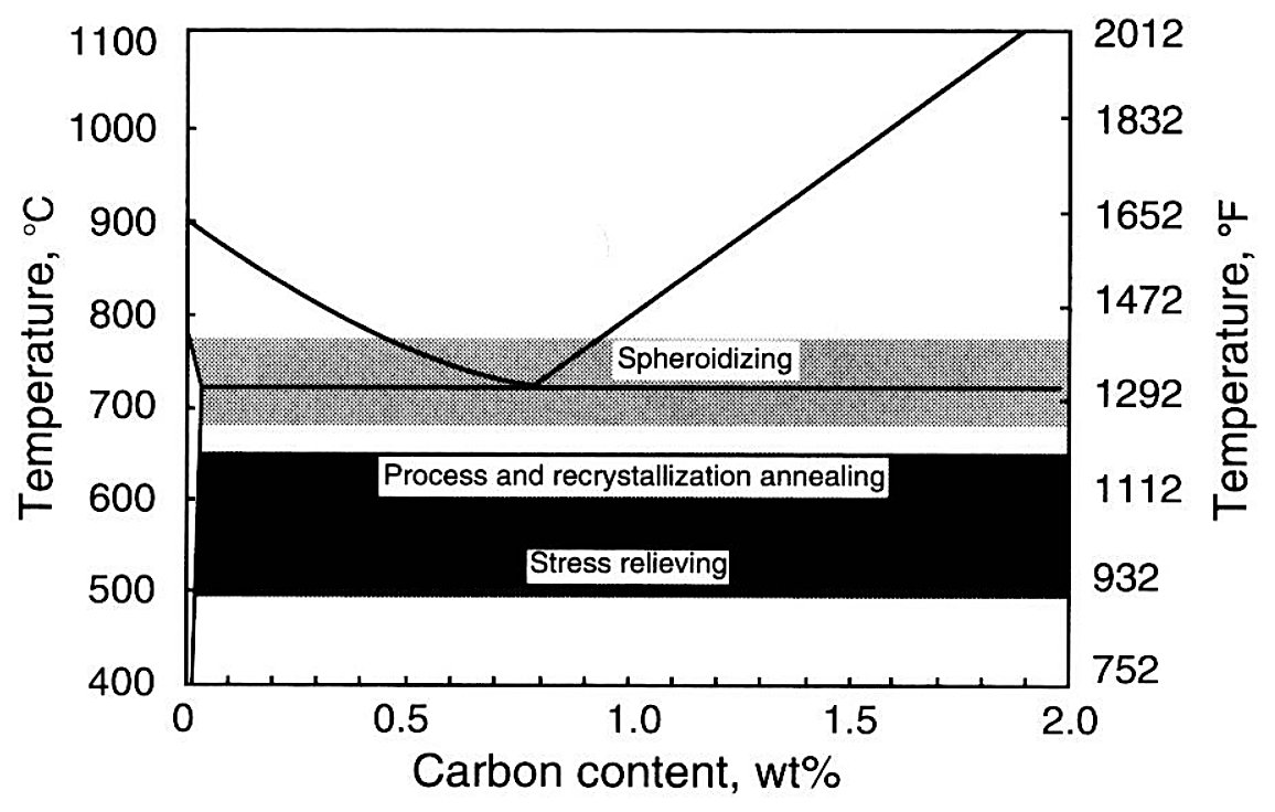
What that hold produces is visible on the microstructure, and it is the structure the annealed stock is sold in.

Heating time to reach the tempering temperature
A tempering furnace is set to a temperature and the load needs a stated number of minutes per millimetre of section to arrive at it. The allowance depends on the shape of the part and on whether the furnace has forced circulation. Table 3 gives the source figures for a hot air oven without circulation and for a circulating air oven or an oil bath.
| Tempering temperature, °C | Tempering temperature, °F | Hot air oven without circulation (a) | Circulating air oven or an oil bath (b) | ||||||||||
|---|---|---|---|---|---|---|---|---|---|---|---|---|---|
| Cubes or spheres | Squares or cylinders | Average flats | Cubes or spheres | Squares or cylinders | Average flats | ||||||||
| min/mm | min/in. | min/mm | min/in. | min/mm | min/in. | min/mm | min/in. | min/mm | min/in. | min/mm | min/in. | ||
| 120 | 250 | 1.2 | 30 | 2.2 | 55 | 3.2 | 80 | 0.6 | 15 | 0.8 | 20 | 1.2 | 30 |
| 150 | 300 | 1.2 | 30 | 2.0 | 50 | 3.0 | 75 | 0.6 | 15 | 0.8 | 20 | 1.2 | 30 |
| 175 | 350 | 1.2 | 30 | 2.0 | 50 | 2.8 | 70 | 0.6 | 15 | 0.8 | 20 | 1.2 | 30 |
| 205 | 400 | 1.0 | 25 | 1.8 | 45 | 2.6 | 65 | 0.6 | 15 | 0.8 | 20 | 1.2 | 30 |
| 260 | 500 | 1.0 | 25 | 1.6 | 40 | 2.4 | 60 | 0.6 | 15 | 0.8 | 20 | 1.2 | 30 |
| 315 | 600 | 1.0 | 25 | 1.6 | 40 | 2.2 | 55 | 0.6 | 15 | 0.8 | 20 | 1.2 | 30 |
| 370 | 700 | 0.8 | 20 | 1.4 | 35 | 2.0 | 50 | 0.6 | 15 | 0.8 | 20 | 1.2 | 30 |
| 425 | 800 | 0.8 | 20 | 1.2 | 30 | 1.8 | 45 | 0.6 | 15 | 0.8 | 20 | 1.2 | 30 |
| ≥480 | ≥900 | 0.8 | 20 | 1.2 | 30 | 1.6 | 40 | 0.6 | 15 | 0.8 | 20 | 1.2 | 30 |
Source, Table 7 of Introduction to Heat Treating of Tool Steels. Data are given in minutes per millimetre, and in minutes per inch, of diameter or thickness, with the furnace held at the temperature in the first column. The source allows the same allowance to be applied to charges of irregular shapes and quantities by estimating the total size of the charge and the number of inches from the outside to the centre of the charge.
Automated salt bath lines
Production heat treating of high speed steel drills, taps and milling cutters is often run on a chain conveyor line with preheat, high heat, quench, wash and rinse stations. The parts travel on tong fixtures, and every station in the line except the air cool is held for one cycle time. Table 4 gives the stage temperatures and the multiples of the cycle time, and Table 5 gives the cycle time for a range of drill diameters and for end mills and cups.
| Process stage | Operating temperature, °C | Operating temperature, °F | Total time in furnace (a) |
|---|---|---|---|
| First preheat | 650-870 | 1200-1600 | X |
| Second preheat | 760-1040 | 1400-1900 | X |
| High heat | 1010-1290 | 1850-2350 | X |
| Isothermal quench | 540-705 | 1000-1300 | X |
| Air cool | Room temperature | Room temperature | 6X, 12X, 24X |
| Wash, hot water | 80-95 | 180-200 | 6X |
| Rinse, hot water | 80-95 | 180-200 | X |
Source, Table 2 of Processes and Furnace Equipment for Heat Treating of Tool Steels. X is the cycle time of the line. The source notes that a nitrate quench after the neutral salt quench cuts the air cooling time from 24X to 6X, and warns that as little as 600 ppm of nitrate salts carried into the high heat furnace causes severe surface damage.
| Drill diameter, mm | Drill diameter, in. | Time |
|---|---|---|
| 2.54-4.78 | 0.100-0.188 | 1 min 30 s |
| 4.80-8.08 | 0.189-0.318 | 1 min 40 s |
| 8.10-12.90 | 0.319-0.508 | 1 min 50 s |
| 12.93-18.24 | 0.509-0.718 | 2 min 0 s |
| 18.26-23.32 | 0.719-0.918 | 2 min 20 s |
| 23.34-38.10 | 0.919-1.500 | 2 min 40 s |
| 102 mm (4 in.) diameter cups | 6 min | |
| 64 mm (2 1/2 in.) diameter end mills | 7 min | |
| 76 mm (3 in.) diameter end mills | 10 min |
Source, Table 3 of Processes and Furnace Equipment for Heat Treating of Tool Steels. High heat times for the line in Table 4. The same table lists how many pieces of each small diameter are loaded per tong, and the source gives the figures below.
| Diameter of the pieces in high heat | Load |
|---|---|
| 2.54 mm (0.100 in.) | 160 pieces per tong, 480 pieces in bath, 1.2 kg (2.6 lb) |
| 4.78 mm (0.188 in.) | 85 pieces per tong, 255 pieces in bath, 3.5 kg (7.65 lb) |
| 6.50 mm (0.256 in.) | 63 pieces per tong, 188 pieces in bath, 5.6 kg (12.3 lb) |
| 8.08 mm (0.318 in.) | 25 pieces per tong, 75 pieces in bath, 3.9 kg (8.6 lb) |
| 12.90 mm (0.508 in.) | 16 pieces per tong, 48 pieces in bath, 8.3 kg (18.2 lb) |
Source, Table 3 of Processes and Furnace Equipment for Heat Treating of Tool Steels. Load weights for the small diameters on the automated line.
Furnace atmosphere dew point
Hardening in a controlled atmosphere protects the surface of the tool, and the protection depends on the carbon potential of the gas. For an AGA class 302 endothermic atmosphere the practical control is the dew point. The ranges in Table 7 are quoted for short times at temperature, which suits small tools. The source warns that a large die section needs closer control of the same atmosphere, because the cycle is long enough for a small carbon imbalance at the surface to grow into a carburized or a decarburized case.
| Steel | Furnace temperature, °C | Furnace temperature, °F | Dew point range, °C | |
|---|---|---|---|---|
| Dew point, °C | Dew point, °F | |||
| W2, W3 | 800 | 1475 | 7 to 13 | 45 to 55 |
| S1 | 925 | 1700 | 4 to 7 | 40 to 45 |
| S2 | 870 | 1600 | 4 to 16 | 40 to 60 |
| O1 | 800 | 1475 | 7 to 12 | 45 to 55 |
| O2 | 775 | 1425 | 7 to 12 | 45 to 55 |
| O7 | 855 | 1575 | -4 to 2 | 25 to 36 |
| D2, D4 | 995 | 1825 | -7 to -1 | 20 to 30 |
| D3, D6 | 955 | 1750 | -7 to -1 | 20 to 30 |
| H11, H12, H13 | 1010 | 1850 | 2 to 7 | 35 to 45 |
| T1 | 1290 | 2350 | -18 to -12 | 0 to 10 |
| M1 | 1205 | 2200 | -15 to -12 | 5 to 10 |
| F2, F3 | 830 | 1525 | 5 to 1 | 23 to 34 |
Source, Table 4 of Processes and Furnace Equipment for Heat Treating of Tool Steels. Data compiled for short times at temperature, with furnace dew point quoted for an AGA class 302 endothermic atmosphere. The source prints the Celsius dew point range for F2 and F3 as 5 to 1 while the Fahrenheit range for the same row is 23 to 34, and the two do not agree, so the row is reproduced exactly as printed.
Packing compounds for annealing
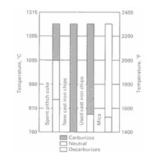
When a tool is annealed in a pack, the compound packed around it sets the carbon level at the surface of the steel. Fig. 2 shows the temperature range in which each of the common compounds carburizes, holds a neutral condition or decarburizes the steel. The source notes that the changes from one behaviour to another are gradual, and that the temperature at which used cast iron chips begin to decarburize depends on the carbon content of the chips.
What these tables do not fix
Each table describes the practice of the plant or the source that produced it, so the numbers are a starting point for a process sheet, and the process sheet still has to be written for the tool in hand. Section size, part geometry, the furnace load, the condition of the quench tank and the thermocouple position all move the result. A new tool should have its hardness checked on a first article before the cycle is released to production, and a change of steel supplier is enough reason to check it again. The alloying and the annealed structure of the bar going into the furnace have as much effect on the outcome as the cycle written on the card.
Source: ASM Handbook, Volume 4, Heat Treating, ASM International, 1991.